Light Touch Switches/EVQPU
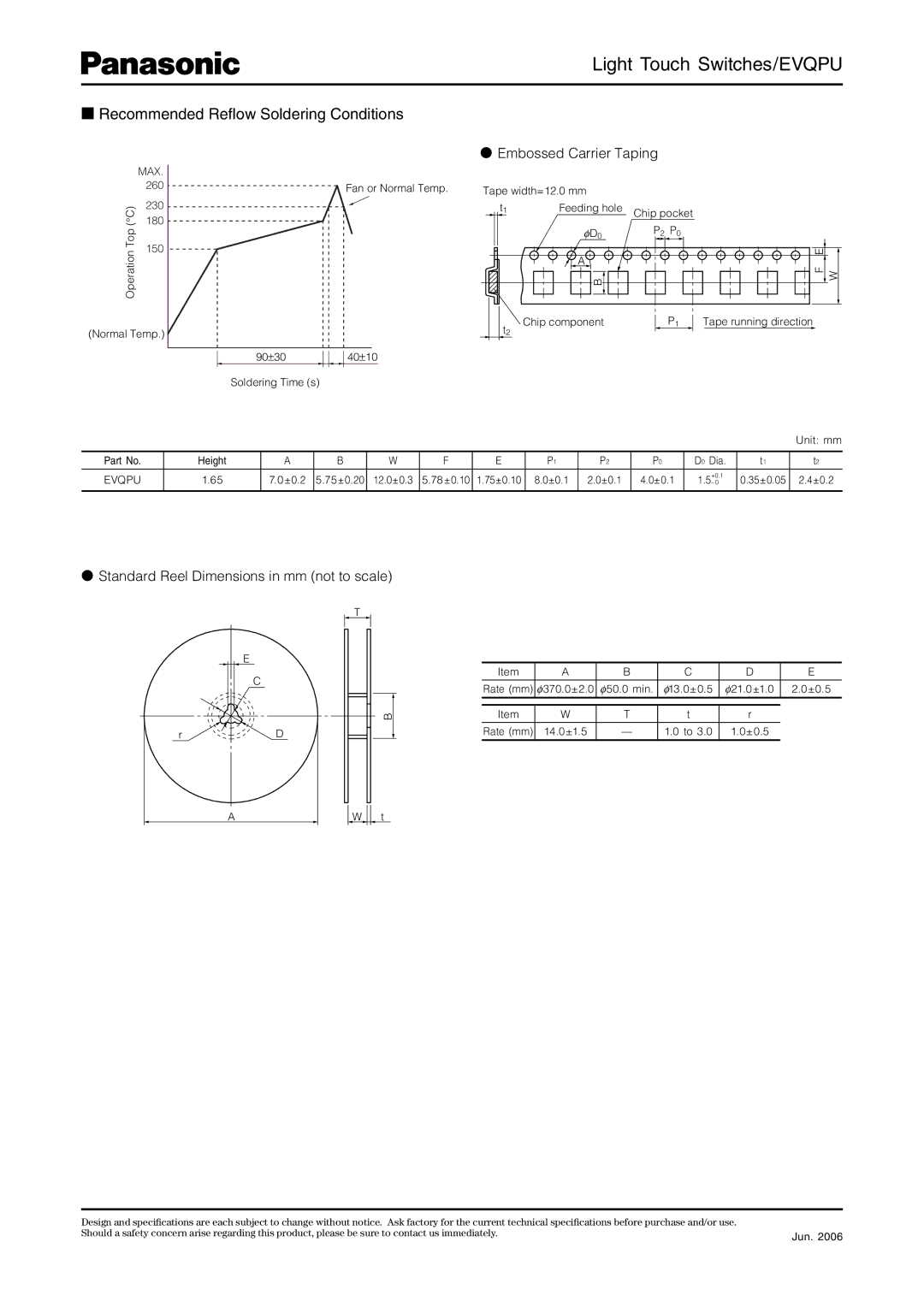
■Recommended Reflow Soldering Conditions
|
|
| ● Embossed Carrier Taping |
| ||
| MAX. |
|
|
|
|
|
| 260 | Fan or Normal Temp. | Tape width=12.0 mm |
|
| |
(°C) | 230 |
| t1 | Feeding hole | Chip pocket | |
180 |
| |||||
|
| φD0 | P2 | P0 | ||
Top |
|
|
| |||
150 |
|
|
|
|
| |
Operation |
|
| B |
|
| |
|
|
|
|
| ||
|
|
|
| A |
|
|
(Normal Temp.) |
| t2 | Chip component |
| P1 | |
|
|
|
| |||
| 90±30 | 40±10 |
|
|
|
|
| Soldering Time (s) |
|
|
|
|
|
W
F E
Tape running direction
|
|
|
|
|
|
|
|
|
|
|
| Unit: mm |
Part No. | Height | A | B | W | F | E | P1 | P2 | P0 | D0 Dia. | t1 | t2 |
|
|
|
|
|
|
|
|
|
|
|
|
|
EVQPU | 1.65 | 7.0±0.2 | 5.75±0.20 | 12.0±0.3 | 5.78±0.10 | 1.75±0.10 | 8.0±0.1 | 2.0±0.1 | 4.0±0.1 | 0.35±0.05 | 2.4±0.2 | |
|
|
|
|
|
|
|
|
|
|
|
|
|
●Standard Reel Dimensions in mm (not to scale)
T
E
C
B
rD
Item | A | B | C | D | E |
|
|
|
|
|
|
Rate (mm) | φ370.0±2.0 | φ50.0 min. | φ13.0±0.5 | φ21.0±1.0 | 2.0±0.5 |
|
|
|
|
|
|
|
|
|
|
|
|
Item | W | T | t | r |
|
|
|
|
|
|
|
Rate (mm) | 14.0±1.5 | — | 1.0 to 3.0 | 1.0±0.5 |
|
A
W ![]()
![]() t
t
Design and specifications are each subject to change without notice. Ask factory for the current technical specifications before purchase and/or use. |
|
Should a safety concern arise regarding this product, please be sure to contact us immediately. | Jun. 2006 |
|