EY7541 specifications
The Panasonic EY7541 is a versatile and powerful cordless impact wrench designed for professionals and enthusiasts seeking reliability and performance in their tools. With a robust build and advanced technology, this tool stands out in the competitive landscape of power tools, particularly for automotive, construction, and industrial applications.One of the standout features of the EY7541 is its impressive 18V lithium-ion battery system, which offers extended runtime and quick charging capabilities. This ensures that users can work longer without frequent interruptions, making it ideal for heavy-duty tasks. The tool is equipped with a compact design, lending it the maneuverability required for tight spaces, while still providing substantial torque and power.
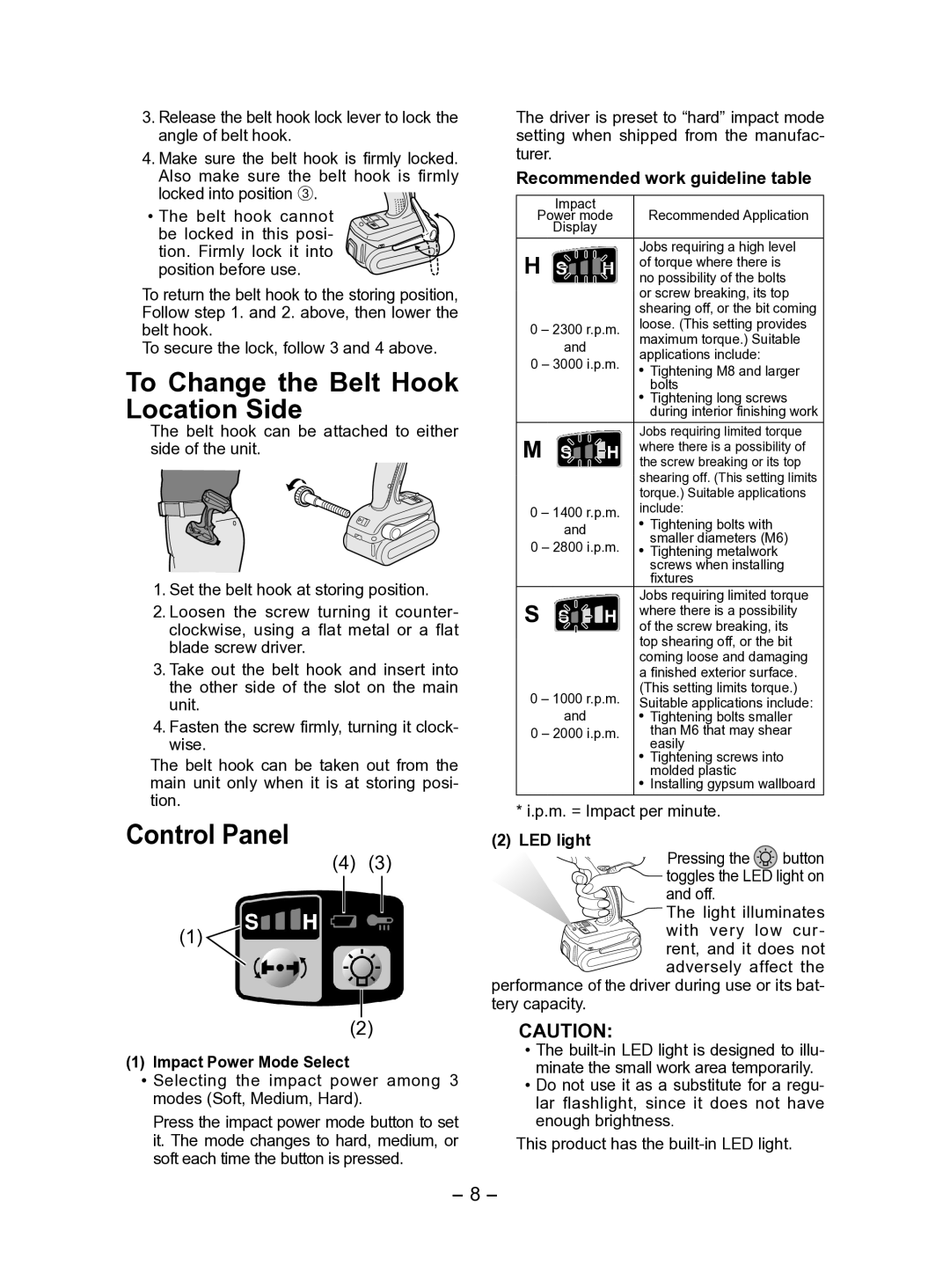
The EY7541 boasts a powerful motor that delivers high torque output, making it suitable for driving large bolts and fasteners efficiently. Its dual speed settings allow users to adjust the wrench's performance based on their specific job requirements. The first speed is ideal for precision work or driving smaller screws, while the second speed maximizes the power for tougher applications, ensuring versatility across various tasks.
Another key characteristic of the Panasonic EY7541 is its ergonomic design. The tool features a comfortable grip that reduces fatigue during extended use, allowing for improved productivity and ease of operation. The weight distribution of the tool also enhances stability, which is crucial for maintaining control during high-speed applications.
Durability is a hallmark of the Panasonic brand, and the EY7541 is no exception. Built with high-quality materials, this impact wrench is designed to withstand the rigors of demanding work environments. The robust housing protects the internal components from damage, and the tool's design includes protective features to prevent overheating.
Moreover, the EY7541 incorporates advanced safety technologies, including an overload protection system that helps prevent damage to the motor, ensuring longevity and consistent performance. The inclusion of LED lights enhances visibility in low-light conditions, allowing users to work effectively even in challenging environments.
In conclusion, the Panasonic EY7541 impact wrench is a reliable tool that integrates power, efficiency, and user-centric features. With its advanced battery technology, variable speed settings, ergonomic design, and durability, it is a top choice for professionals in need of a high-performing impact wrench that can handle a variety of tasks with ease.

