
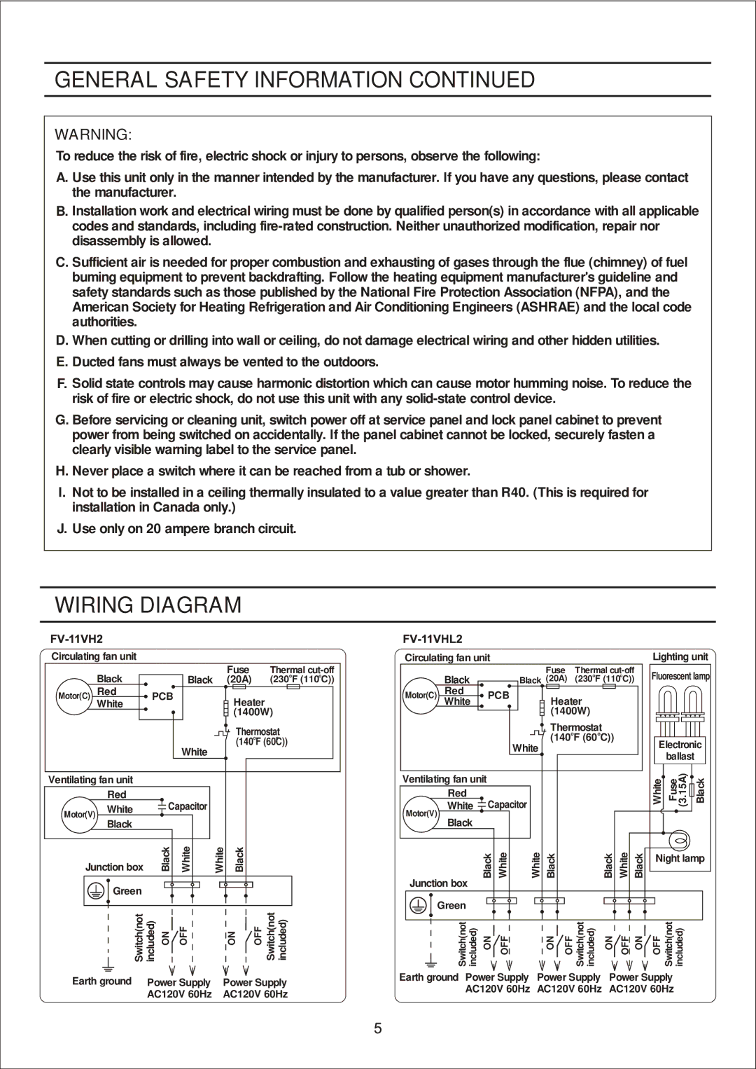
FV-11VH2 specifications
The Panasonic FV-11VH2 is an innovative and highly efficient ventilation fan designed to enhance indoor air quality in residential spaces. This unit is particularly suitable for bathrooms and small utility rooms, where moisture accumulation can lead to mold and mildew growth. With its advanced features and technologies, the FV-11VH2 stands out as a reliable choice for homeowners seeking improved ventilation solutions.One of the main features of the FV-11VH2 is its powerful airflow capacity of 110 cubic feet per minute (CFM), which efficiently circulates air in spaces up to 110 square feet. This makes it ideal for use in standard bathrooms, ensuring that humidity is effectively reduced after showers or baths. The fan operates quietly, producing only 0.6 sones, allowing for comfortable environments without disruptive noise.
The FV-11VH2 is equipped with a number of innovative technologies. The built-in Pick-A-Flow speed selector allows users to choose their desired CFM, providing flexibility to meet specific ventilation needs. The fan can operate at either high or low speed depending on the level of moisture detected in the air, ensuring optimal performance and energy efficiency.
Another significant characteristic of the FV-11VH2 is its energy-efficient design. It is Energy Star rated, which means it meets strict energy efficiency guidelines set by the U.S. Environmental Protection Agency. This certification not only helps reduce electricity costs but also contributes to a more sustainable living environment.
The Panasonic FV-11VH2 also features a robust construction, including a durable steel housing and a compact design that can be installed easily in various ceiling structures. The fan is designed for long-lasting performance, with a rated lifespan of up to 50,000 hours, which ensures that it will serve homeowners effectively for years to come.
Installation flexibility is another notable aspect of the FV-11VH2. The fan can be mounted in a variety of orientations, whether vertically or horizontally, making it suitable for different residential layouts. Additionally, the unit includes an easy-to-clean, washable filter that helps to trap dust and allergens, further improving indoor air quality.
In summary, the Panasonic FV-11VH2 represents a perfect blend of performance, efficiency, and convenience. With its powerful airflow, quiet operation, energy-saving technologies, and durable construction, it is an excellent choice for anyone looking to maintain a healthy indoor environment.