KX-TC1205RUB / KX-TC1205R UW / KX-TC1205R US / KX-TC1205RUF
16.2. Power Supply Circuit
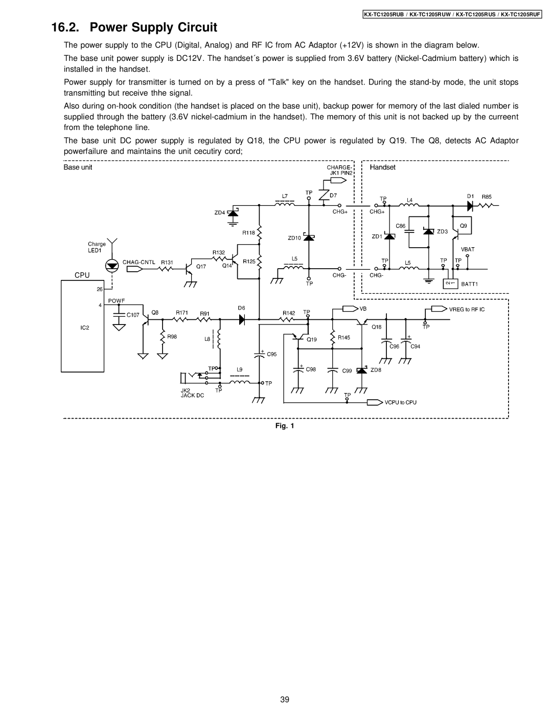
The power supply to the CPU (Digital, Analog) and RF IC from AC Adaptor (+12V) is shown in the diagram below.
The base unit power supply is DC12V. The handset´s power is supplied from 3.6V battery
Power supply for transmitter is turned on by a press of "Talk" key on the handset. During the
Also during
The base unit DC power supply is regulated by Q18, the CPU power is regulated by Q19. The Q8, detects AC Adaptor powerfailure and maintains the unit cecutiry cord;
Fig. 1
39
