FP-e Series
Specification table
5

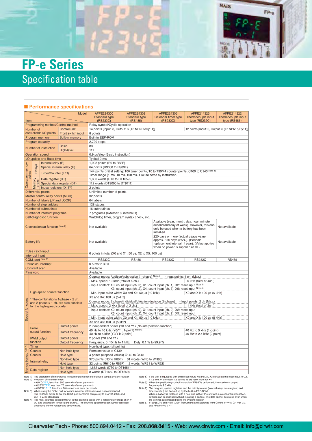
Performance specifications

Note 1)
Note 2)
Note 3)
Note 4)
Note 5)
Note 6)
Note 7)
Note 8)
The proportion of timer points to counter points can be changed using a system register.
Precision of calendar timer:
- At 0°C/32°F, less than 200 seconds of error per month
- At 25°C/77°F, less than 70 seconds of error per month
- At 55°C/131°F, less than 240 seconds of error per month
When using the COM. port for communication, retransmission is recommended.
The RS232C driver IC for the COM. port conforms completely to EIA/TIA-232E and
CCITT V. 28 standards
The max. counting speed (10 kHz) is the counting speed with a rated input voltage of 24 V
DC and an ambient temperature of 25°C. The counting speed (frequency) will decrease
depending on the voltage and temperature.
If the unit is equipped with both reset inputs X0 and X1, X2 serves as the reset input for X1.
If X3 and X4 are used, X5 serves as the reset input for X4.
When the positioning control instruction “F168” is performed, the maximum output
frequency is 9.5 kHz.
The program, system registers and the hold type area (internal relay, data register, and
timer/counter) are backed up by the built-in EEP-ROM.
When a battery is replaced with a new one in the FP-e unit with a calendar timer function,
settings can be changed without installing a battery. The data cannot be stored even when
the settings are changed using the system register.
F180 (SCR) and F181 (DSP) instructions are supported from Control FPWIN GR Ver. 2.2.
and FPWIN Pro V 4.1.
Relay symbol/Cyclic operation
14 points [Input: 8, Output: 6 (Tr. NPN: 5/Ry: 1)]
8 points
Built-in EEP-ROM
2,720 steps
83
117
0.9 µs/step (Basic instruction)
Typical 2 ms
1,008 points (R0 to R62F)
64 points (R9000 to R903F)
Item
Model
12 points [Input: 6, Output: 6 (Tr. NPN: 5/Ry: 1)]
Control unit
Front switch input
Built-in memory
Basic
High-level
144 points (Initial setting: 100 timer points, T0 to T99/44 counter points, C100 to C143 Note 1)
Timer range (1 ms, 10 ms, 100 ms, 1 s): selected by instruction
1,660 words (DT0 to DT1659)
112 words (DT9000 to DT9111)
2 points
Unlimited number of points
32 points
64 labels
128 stages
16 subroutines
7 programs (external: 6, internal 1)
Watchdog timer, program syntax check, etc.
Not available
Not available
Available (year, month, day, hour, minute,
second and day of week). However, this can
only be used when a battery has been
installed.
220 days or more (actual usage value:
approx. 870 days (25°C). (Periodic
replacement interval: 1 year). (Value applies
when no power is supplied at all.)
Not available
Not available
6 points in total (X0 and X1: 50 µs, X2 to X5: 100 µs)
Programming method/Control method
Number of
controllable I/O points
Program memory
Program capacity
Number of instruction
Operation speed
I/O update and Base time
Internal relay (R)
Special internal relay (R)
Timer/Counter (T/C)
Data register (DT)
Special data register (DT)
Index registers (IX. IY)
Differential points
Master control relay points (MCR)
Number of labels (JP and LOOP)
Number of step ladders
Number of subroutines
Number of interrupt programs
Self-diagnostic function
Clock/calendar function Note 2)
Battery life
Pulse catch input
Interrupt input
COM. port Note 3)
Periodical interrupt
Constant scan
Password
0.5 ms to 30 s
Available
Available
Counter mode: Addition/subtraction (1-phase) Note 4) - Input points: 4 ch. (Max.)
- Max. speed: 10 kHz (total of 4 ch.)
- Input contact: X0: count input (ch. 0), X1: count input (ch. 1), X2: reset input Note 5)
X3: count input (ch. 2), X4: count input (ch. 3), X5: reset input Note 5)
2 independent points (Y0 and Y1) (No interpolation function)
- Min. input pulse width: X0 and X1: 50 µs (10 kHz)
X3 and X4: 100 µs (5kHz)
Counter mode: 2-phase/individual/direction decision (2-phase) - Input points: 2 ch (Max.)
- Max. speed: 2 kHz (total of 2 ch.)
- Input contact: X0: count input (ch. 0), X1: count input (ch. 0), X2: reset input
X3: count input (ch. 2), X4: count input (ch. 2), X5: reset input
- Min. input pulse width: X0 and X1: 50 µs (10 kHz)
X3 and X4: 100 µs (5 kHz)
High-speed counter function
* The combinations 1-phase × 2 ch.
and 2-phase × 1 ch. are also possible
for the high-speed counter.
Pulse
output function 40 Hz to 10 kHz (Y0/Y1: 1-point) Note 6)
40 Hz to 5 kHz (Y0/Y1: 2-point)
X0 and X1: 100 µs (5 kHz)
: 5 kHz (total of 4ch.)
: 1 kHz (total of 2ch.)
X0 and X1: 100 µs (5 kHz)
40 Hz to 5 kHz (1-point)
40 Hz to 2.5 kHz (2-point)
2 points (Y0 and Y1)
Frequency: 0. 15 Hz to 1 kHz Duty: 0.1 % to 99.9 %
Non-hold type: (all points)
From set value to C139
4 points (elapsed values) C140 to C143
976 points (R0 to R60F) 61 words (WR0 to WR60)
32 points (R610 to R62F) 2 words (WR61 to WR62)
1,652 words (DT0 to DT1651)
8 words (DT1652 to DT1659)
PWM output
function
Output points
Output frequency
Timer
Counter
Counter
Output points
Output frequency
Non-hold type
Hold type
Non-hold type
Hold type
Non-hold type
Hold type
Internal relay
Data register
AFPE224300
Standard type
(RS232C)
AFPE224302
Standard type
(RS485)
AFPE224305
Calendar timer type
(RS232C)
AFPE214325
Thermocouple input
type (RS232C)
AFPE214322
Thermocouple input
type (RS485)
RS232C RS485 RS232C RS232C RS485
Memory backup Note 7)
Special functions Operation memory
points
Memory
areas Relays

Clearwater Tech - Phone: 800.894.0412 - Fax: 208.368.0415 - Web: www.clrwtr.com - Email: info@clrwtr.com

01/2004