USA
Multimedia Projection Display Operating Instructions
For assistance, please call
Follow all instructions carefully
Keep these instructions for future reference
Trademarks
Models Number
For assistance, please call 1-888-VIEW PTV843-9788
Or send e-mail to consumerproducts@panasonic.com
Declaration of Conformity
Table of Contents
Optional External Equipment
Before Using
Safety Precaution
Receiver Location
Observe the following precautions
Accessories
Remote Control Battery Installation
Before Using
Location of Controls
Illuminated Remote Control
Location of Controls
Model PT-50LC13 unit shown
Controls and Terminals on the projection display
Vent
Antenna Connection
Installation
Connecting the Antenna / Cable to the RF in Terminal No VCR
Cable Connection
Installation
Connecting the Antenna / Cable to the RF in Terminal VCR
Connects VCRs and other peripheral equipment
How to connect the 1, 2, 3 Input Terminals
Display
Component Signals Y, PB, PR that can be Input
Signal data Information menu Mode type No. of dots
Vertical frequency
How to connect the AV Out Terminals
NC Not connected Pin No Signal name
How to connect the RGB in Terminals
Connecting a PC to RGB
Pin No Signal name
Audio cable RGB cable D-SUB 15P
Connecting a DTV Decoder to RGB
GND
How to connect the Digital in Terminal
Connecting a DTV Decoder to Digital
Digital in Terminal Pin Layouts
Computer
RGB/DIGITAL in signals that can be input
Signals
DTV Format Signals
When setup is complete, the lowest channel picture appears
Power on and OFF
Initial Setup
If using Cable Box, DSS Receiver, or VCR
Power OFF
Turning the Power on and OFF
Power on / OFF
Power on
Select Menu desired by
Flow Chart of Main menu
Returning to the previous screen
Flow Chart of Main menu
Adjust items Set an item Select an item
On the next
Tuning channels
Automatic channel setting
Press to exit menu
Tuning channels
When setup is complete, the lowest channel picture
Appears
Press to display the Manual SET screen
Manual channel setting
Press to select TV or Cable
Manual SET
Press to add channels to memory
To add channel
To delete channel
Press to select channel
Desired Channel. Or use Number keys
Press to Select Desired Volume Level
Projection display operation
Operation can be done from the projection display
Auto shut off
Using the number keys
Projection display operation
TV status display
Normal Full True
Aspect Controls
Just Normal Zoom Full
Normal Zoom Full
Just
Mode Picture Explanation
Normal will display a 43 picture at its
Standard 43 size
Channel up and down buttons
When a channel button is pressed during channel search
Video Component Card Digital RGB
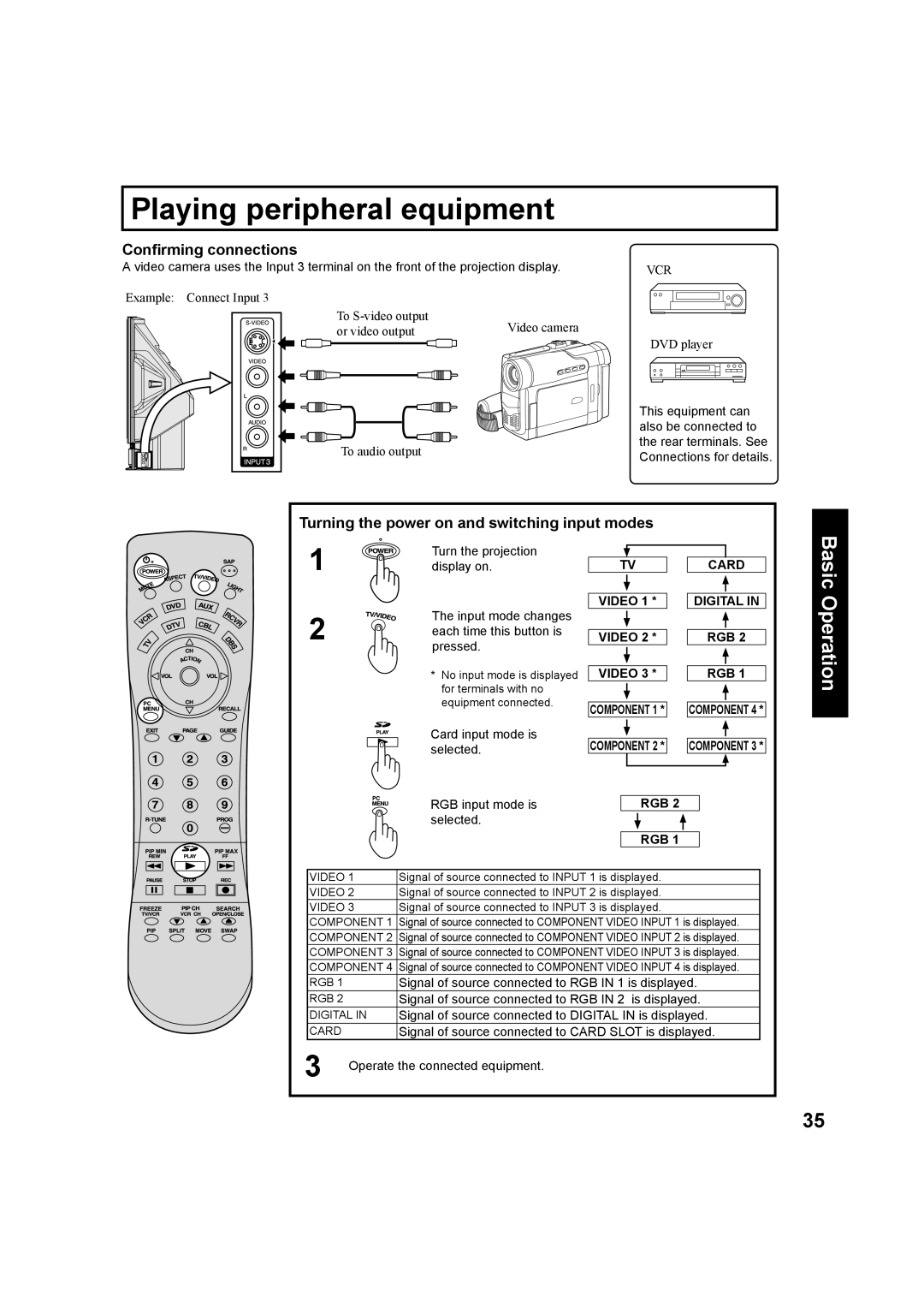
Turning the power on and switching input modes
Playing peripheral equipment
Confirming connections
Freezing pictures
Mute / Freeze / SAP
Sound mute
SAP
Select Audio Mode for TV Viewing
Mute / Freeze / SAP
Receivable Broadcast Types
Press to return
Split screen
Splitting the screen
Selecting the screen aspect for split screen
Video
Split screen
Changing the channel of the right screen
Swapping left and right screens
Display PIP screen
Picture in Picture PIP Screen
You can move the PIP screen to four positions
Picture in Picture PIP Screen
Changing the channel of the PIP screen
Move PIP screen
POSITION/SIZE
Adjusting screen position and size
Adjust
Widen Narrow
Adjusting screen position and size
Phase
Enlarge Shrink
Normal Auto Cinema Music Speech
Audio Adjustments
Audio
Treble
Audio Adjustments
Using BBE
Bass
Warm
Picture Adjustments
Picture
Dynamic
Picture Adjustments
Lock
Lock Feature
Or Or
Enter Secret Code
View NR Not Rated
Lock Feature
Setup US Movies Ratings
Perform Enter Secret Code on
Programs
Setup US TV Programs Ratings
Perform US Movies Ratings on
US TV
Restricted
General Audience
Parental Guidance Suggested
Parents Cautioned
No OFF CAP C1 Text C1 CAP C2 Text C2
Caption Mode Text C1 or C2
Caption Mode OFF
Closed Captions
No OFF CAP C1 CAP C2
Closed Captions
CC on Mute
Press repeatedly to select
Channel Caption
Channel Caption Feature
Display
Weak Signal Display Feature
Video NR
Video NR Noise Reduction Feature
Video
Press to display the Video screen
Automatically changing screen size
VGA
RGB/DIGITAL in Input Feature
RGB
Digital
Set to OFF if picture appears
3D Y/C Feature
3D IP Feature
OFF
OFF
Sleep Timer Feature
Sleep Timer
Other
Information
Switching languages for display
Information
English Español Français
Press to display the Other screen
Demo Mode Feature
Demo Mode
Folders and Files
Jpeg Viewer SD Card/PC Card
Card Data Protection
Card Menu Screen
Jpeg Viewer SD Card/PC Card
Insert the Card
Remove the Card
Return Operation
Menu Area Operation
Index Area Operation
Press Left column of next
Single Play Mode
Press to display next/previous page of 9 thumbnail files
Press Action to display file in full screen size
From
Slide Show Mode
Picture Adjustment
Information Screen Display
Lamp has a maximum life of about 10 000 hours
Lamp unit replacement period
Replacing the lamp unit
Rcvr
VCR
CBL
DBS
Cable
When code is not known
Infrared Remote Codes for Specific Components
VCR Infrared Codes Index
Maker Set Up No
Maker List CBL
Maker List Personal Video Recorders
Button
Quick Reference Functional Button Chart
Mode Function
Button Mode Function
Symptoms Checks
Troubleshooting
PT-50LC13 PT-60LC13
Specifications
Customer Services Directory
Cleaning
Category Parts Labor Service
Limited Warranty
Panasonic Multimedia Projection Display Limited Warranty
Customer’ Record
Power button/POWER indicator 10, 23
Index
Channel up / down buttons projection display