MA Motion Sensor (AMA1, AMB1, 2, 3)
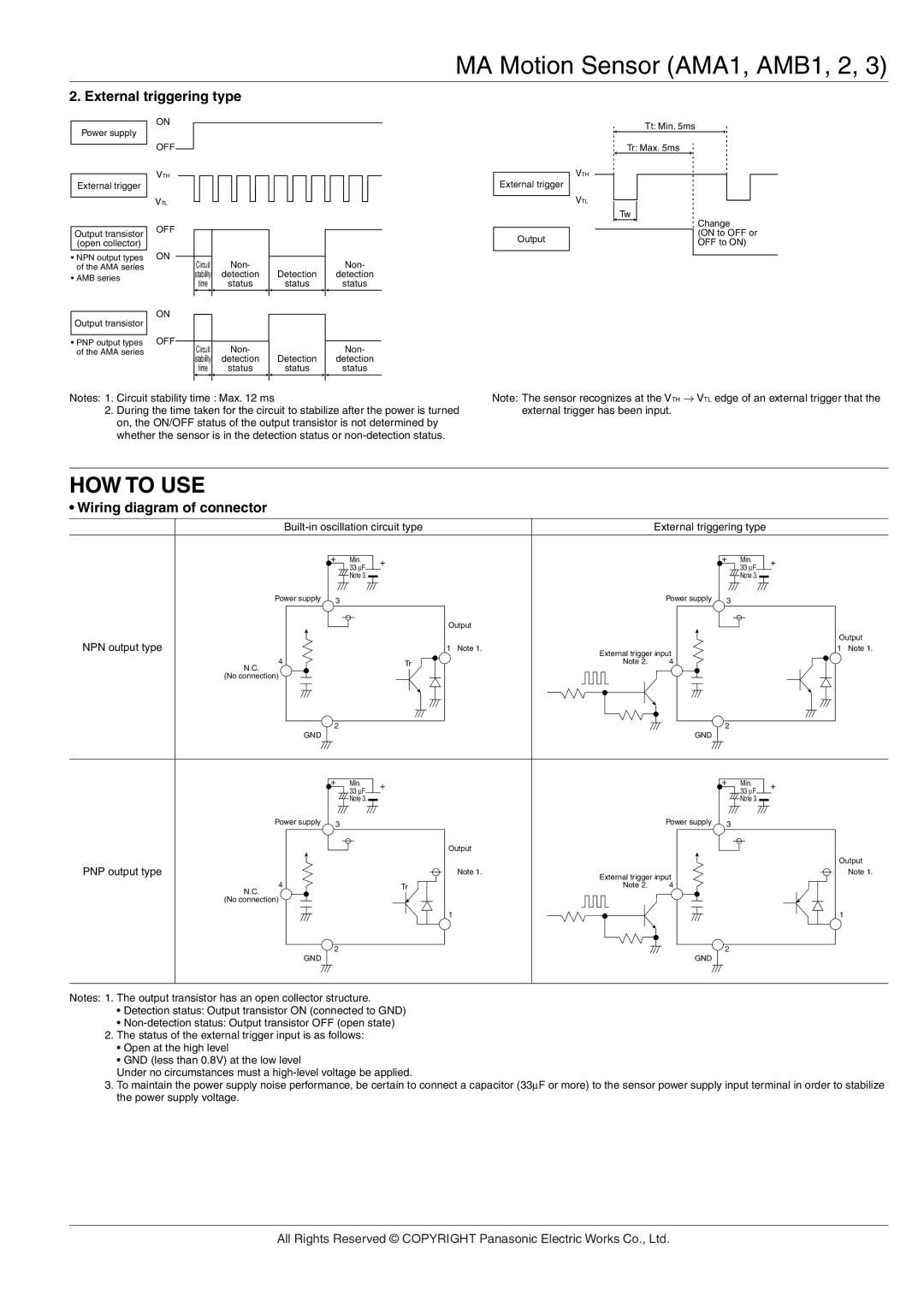
2. External triggering type
Power supply
External trigger
Output transistor (open collector)
•NPN output types of the AMA series
•AMB series
Output transistor
•PNP output types of the AMA series
ON
OFF
VTH
VTL
OFF
ON
ON
OFF
| Circuit | Non- |
|
| Non- | |
| stability | detection | Detection |
| detection | |
| time | status | status |
| status | |
|
|
|
|
|
|
|
|
|
|
|
|
|
|
| Circuit | Non- |
|
| Non- | |
| stability | detection | Detection |
| detection | |
| time | status | status |
| status | |
|
|
|
|
|
|
|
External trigger
Output
VTH
VTL
Tt: Min. 5ms
Tr: Max. 5ms
Tw
Change
(ON to OFF or OFF to ON)
Notes: 1. Circuit stability time : Max. 12 ms
2.During the time taken for the circuit to stabilize after the power is turned on, the ON/OFF status of the output transistor is not determined by whether the sensor is in the detection status or
Note: The sensor recognizes at the VTH → VTL edge of an external trigger that the external trigger has been input.
HOW TO USE
• Wiring diagram of connector
| External triggering type |
| ||||||
| + | Min. | + |
|
| + | Min. | + |
|
| 33 ∝F |
|
|
| 33 ∝F | ||
|
|
|
|
|
|
| ||
|
| Note 3. |
|
|
|
| Note 3. |
|
Power supply | 3 |
|
|
| Power supply | 3 |
|
|
|
|
|
|
|
|
| ||
|
|
| Output |
|
|
|
|
|
NPN output type |
|
|
|
|
|
|
| Output |
|
| 1 Note 1. | External trigger input |
|
| 1 Note 1. | ||
4 |
|
|
|
|
|
| ||
|
| Tr | Note 2. | 4 |
|
|
| |
N.C. |
|
|
|
|
|
|
|
|
(No connection) |
|
|
|
|
|
|
|
|
| 2 |
|
|
|
| 2 |
|
|
GND |
|
|
|
| GND |
|
|
|
| + | Min. | + |
|
| + | Min. | + |
|
| 33 ∝F |
|
|
| 33 ∝F | ||
|
|
|
|
|
|
| ||
|
| Note 3. |
|
|
|
| Note 3. |
|
Power supply | 3 |
|
|
| Power supply | 3 |
|
|
|
|
|
|
|
|
| ||
|
|
| Output |
|
|
|
|
|
PNP output type |
|
|
|
|
|
|
| Output |
|
| Note 1. | External trigger input |
|
| Note 1. | ||
4 |
|
|
|
|
|
| ||
|
| Tr | Note 2. | 4 |
|
|
| |
N.C. |
|
|
|
|
|
|
|
|
(No connection) |
|
|
|
|
|
|
|
|
|
|
| 1 |
|
|
|
| 1 |
| 2 |
|
|
|
| 2 |
|
|
GND |
|
|
|
| GND |
|
|
|
Notes: 1. The output transistor has an open collector structure.
•Detection status: Output transistor ON (connected to GND)
•
2.The status of the external trigger input is as follows:
•Open at the high level
•GND (less than 0.8V) at the low level
Under no circumstances must a
3.To maintain the power supply noise performance, be certain to connect a capacitor (33µF or more) to the sensor power supply input terminal in order to stabilize the power supply voltage.
All Rights Reserved © COPYRIGHT Panasonic Electric Works Co., Ltd.