MA Motion Sensor (AMA1, AMB1, 2, 3)
2) External triggering type (trigger conditions: trigger pulse width = 20µs and trigger synchronization = 5ms)
|
|
|
|
| Thin short type |
|
|
|
|
|
| |
|
|
|
|
| Note 1 |
|
|
|
|
|
| |
| Items |
| Symbol |
|
| Short type |
| Middle type |
| Long type | Measured conditions | |
|
| NPN | PNP |
|
| |||||||
|
|
|
|
| output | output |
|
|
|
|
|
|
|
|
|
|
| type | type |
|
|
|
|
|
|
|
|
|
|
|
|
|
|
|
|
|
| |
|
|
| Minimum |
|
| 5V DC type: |
|
| ||||
|
|
|
|
|
|
|
|
|
| |||
Rated operating voltage | Typical | Vdd |
|
| — |
|
|
|
| |||
|
|
|
|
|
|
|
|
| ||||
|
|
| Maximum |
|
| 5V DC type: |
|
| ||||
|
|
|
|
|
|
|
|
|
|
|
|
|
|
|
| Minimum |
|
|
| — |
|
|
|
| |
|
|
|
|
|
|
|
|
|
| |||
|
| Output OFF | Typical | Ib | 0.1m | 5V DC type: | Note 2: *b | |||||
|
|
|
|
|
|
|
| |||||
| Without |
| Maximum |
| 0.3m | 5V DC type: |
| |||||
| trigger input |
| Minimum |
|
|
| — |
|
|
|
| |
|
|
|
|
|
|
|
|
|
|
| ||
|
| Output ON | Typical | Id | 2.6mA | 6.7mA | 5V DC type: | Note 2: *d | ||||
|
|
|
|
|
|
|
|
| ||||
Average current |
|
| Maximum |
| 6.6mA | 9.6mA | 5V DC type: |
| ||||
consumption |
|
| Minimum |
|
|
| — |
|
|
|
| |
|
|
|
|
|
|
|
|
|
| |||
|
| Output OFF | Typical | Ia | 2.2mA | 5V DC type: | Note 2: *a | |||||
|
|
|
|
|
|
|
| |||||
| With trigger |
| Maximum |
| 6.2mA | 5V DC type: |
| |||||
| input |
| Minimum |
|
|
| — |
|
|
|
| |
|
|
|
|
|
|
|
|
|
|
| ||
|
| Output ON | Typical | Ic | 4.2mA | 6.2mA | 5V DC type: | Note 2: *c | ||||
|
|
|
|
|
|
|
|
| ||||
|
|
| Maximum |
| 8.2mA | 12.5mA | 5V DC type: |
| ||||
|
|
|
|
|
|
|
|
|
|
|
|
|
Measuring cycle (Trigger interval) | Minimum | Tt |
|
| 5ms/cycle |
|
|
|
| |||
|
|
|
|
|
|
|
|
|
|
|
|
|
| Pulse width | Minimum | Tw |
|
| 20µs |
|
|
|
| ||
|
|
|
|
|
|
|
|
|
| |||
External trigger | Maximum |
|
| 1/2Tt |
|
|
| Half off the distance period | ||||
|
|
|
|
|
|
|
| |||||
|
|
|
|
|
|
|
|
|
|
|
| |
Level | Maximum | VTL |
|
| 0.8V |
|
|
|
| |||
|
|
|
|
|
|
| ||||||
|
|
|
|
|
|
|
|
|
|
| ||
| Minimum | VTH |
|
| 3V |
|
|
| Note 3 | |||
|
|
|
|
|
|
|
| |||||
|
|
|
|
|
|
|
|
|
|
|
|
|
Response performance: | Maximum | Tr |
|
| 5ms |
|
|
|
| |||
time from trigger pulse fall to detection output |
|
|
|
|
|
| ||||||
|
|
|
|
|
|
|
|
|
| |||
|
|
|
|
|
|
|
|
|
|
|
|
|
Output | Remain voltage | Maximum | Vr | 1 V DC | 1.2 V DC |
|
| 1 V |
| I = 10 mA | ||
characteristics | Leakage current | Maximum | Il | 5µA |
|
| 3µA |
| V = 30 mA | |||
|
|
|
|
|
|
|
|
|
|
|
|
|
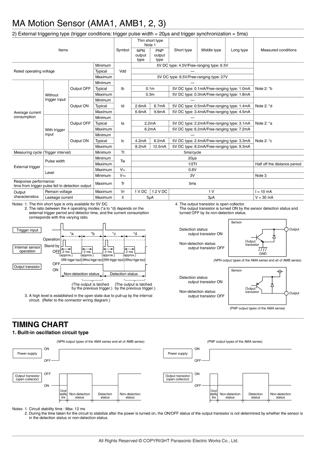
Notes: 1. The thin short type is only available for 5V DC.
2.The ratio between the 4 operating modes (*a to *d) depends on the external trigger period and detector time, and the current consumption corresponds with this varying ratio.
|
|
|
|
|
|
|
|
|
|
|
|
|
|
|
|
|
|
|
|
|
|
Trigger input |
|
|
|
|
|
|
|
|
|
|
|
|
|
|
|
|
|
|
|
|
|
Operation |
|
|
| *a |
|
|
|
| *b |
|
|
| *c |
|
|
| *d |
|
| ||
|
|
|
|
|
|
|
|
|
|
|
|
|
|
| |||||||
|
|
|
|
|
|
|
|
|
|
|
|
|
|
| |||||||
|
|
|
|
|
|
|
|
|
|
|
|
|
|
|
|
|
| ||||
Internal sensor | Stand by |
|
|
|
|
|
|
|
|
|
|
|
|
|
|
|
|
| |||
|
|
|
|
|
|
|
|
|
|
|
|
|
|
|
| ||||||
|
|
|
|
|
|
|
|
|
|
|
|
|
|
|
|
|
|
|
|
| |
operation |
| OFF 2 ms |
| 2 ms |
| 2 ms |
| 2 ms |
| ||||||||||||
|
| (approx.) | (approx.) | (approx.) | (approx.) |
| |||||||||||||||
(With trigger input) (Without trigger input) (With trigger input) (Without trigger input)
4.The output transistor is open collector.
The output transistor is turned ON by the sensor detection status and turned OFF by its
| Sensor |
|
Detection status: |
| Output |
output transistor ON |
|
|
Output |
| |
transistor |
| |
output transistor OFF |
|
|
| GND |
|
|
|
|
(NPN output types of the AMA series and all of AMB series) | ||
Output transistor
OFF
ON
|
|
| Detection status |
|
| |
(The output is latched | (The output is latched | |||||
by the previous trigger.) by the previous trigger.)
Sensor
Detection status: output transistor ON
Output |
| |
transistor | Output |
3.A high level is established in the open state due to
output transistor OFF |
(PNP output types of the AMA series)
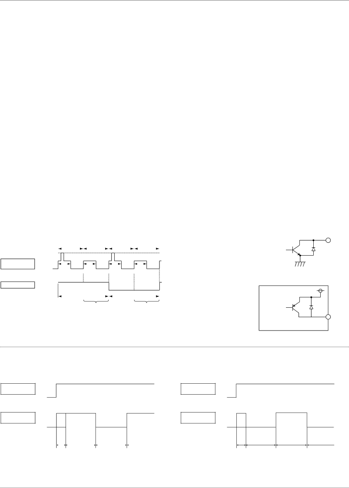
TIMING CHART
1. Built-in oscillation circuit type
(NPN output types of the AMA series and all of AMB series)
ON
Power supply
OFF
Power supply
(PNP output types of the AMA series)
ON
OFF
Output transistor (open collector)
OFF
ON
Output transistor (open collector)
ON
OFF
Circuit |
| Detection |
| ||||
stability |
|
| |||||
| time |
| status |
| status |
| status |
Circuit
stability
time
status
Detection
status
status
Notes: 1. Circuit stability time : Max. 12 ms
2.During the time taken for the circuit to stabilize after the power is turned on, the ON/OFF status of the output transistor is not determined by whether the sensor is in the detection status or
All Rights Reserved © COPYRIGHT Panasonic Electric Works Co., Ltd.