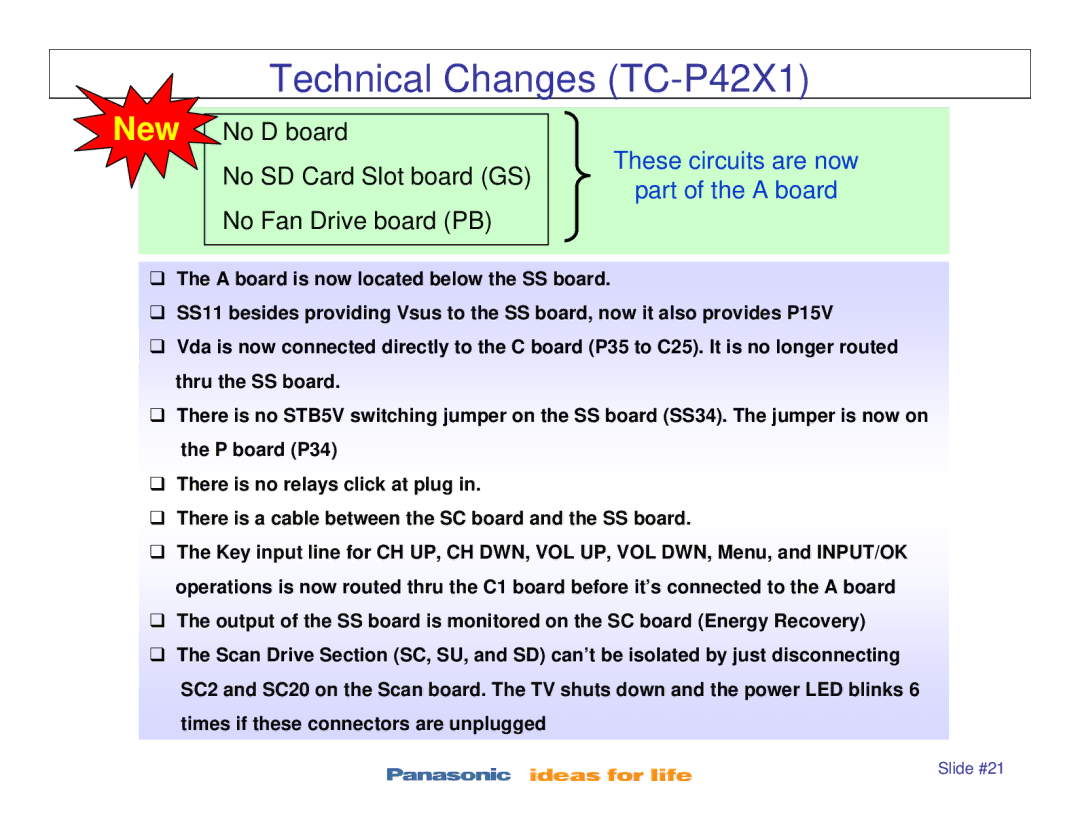
TC-P42X1, TC-P46S1, TC-P50S1, TC-P42S1, TC-P50X1 specifications
The Panasonic TC-P46S1, TC-P50S1, and TC-P54S1 are part of Panasonic's Viera plasma television lineup that has gained a reputation for its superb picture quality and wide viewing angles. These models, introduced in the early 2010s, incorporate several innovative features and technologies that enhance the viewing experience for consumers.First and foremost, each of these models features Panasonic's NeoPDP technology, which allows for deeper blacks and enhanced color accuracy. This technology reduces the size of subpixels, thereby increasing the overall pixel count and improving the display's ability to reproduce finer detail. As a result, users can enjoy a rich and immersive visual experience with vibrant colors and excellent contrast across all lighting conditions.
The TC-P46S1, with a 46-inch screen, the TC-P50S1 at 50 inches, and the TC-P54S1 at 54 inches, cater to various room sizes and viewing preferences, making them versatile options for different home setups. The displays support Full HD 1080p resolution, which guarantees sharp and clear imagery, whether it’s for watching movies, playing video games, or streaming content.
Another standout feature is the Viera Image Viewer, which allows users to view their photos and videos directly on the television using SD memory cards. This feature enhances the television's utility beyond traditional broadcasting, making it a fantastic centerpiece for family gatherings and social events.
These models also include a 600Hz Sub-field Drive technology, which improves motion clarity, reducing blur during fast-paced scenes such as sports or action movies. This technology ensures that viewers can enjoy a smooth cinematic experience without sacrificing detail.
Moreover, the TC-P46S1, TC-P50S1, and TC-P54S1 are designed with energy efficiency in mind, given the increasing emphasis on environmentally friendly electronics. They are equipped with energy-saving features that help reduce power consumption without compromising performance.
Connectivity options further enhance their functionality, with multiple HDMI ports, allowing users to connect various devices easily, from gaming consoles to Blu-ray players.
Overall, the Panasonic TC-P46S1, TC-P50S1, and TC-P54S1 televisions exemplify the blend of advanced imaging technologies and user-friendly features that make them standout choices in the realm of plasma TVs, providing an exceptional viewing experience for movie lovers and casual viewers alike.

