TN

DIMENSIONS (Unit: mm inch)


External dimensions

PC board pattern (Bottom view)

Standard PC board terminal

14


5.6


551


.220

9.89.5

.386 .374

3.5

.138


0.25


2.54

0.5

1.385


.010


.100

.020


.055


2.54


.100

10.16

.400

2.54

.100

2.54

.100

10-1.0 dia. hole

10-.039 dia. hole

Tolerance: ±0.1 ±.004


Self-clinching terminal


Schematic (Bottom view)


14


5.6


Single side stable

1-coil latching

2-coil latching


551


.220


9.8

9.5


1

2 3 4

5

1

2

3

4 5

1 2

3

4

5

.386 .374


3.5


.138


10 9 8

7

6

10 9

8

7 6

10 9

8

7 6


0.25


Direction indication

Direction indication


2.54

0.5

1.385

.010 2.54

Direction indication


.100

.020

.055

.100


General tolerance: ±0.3 ±.012


(Deenergized condition)

(Reset condition)

(Reset condition)


NOTES

1. Coil operating power

Pure DC current should be applied to the coil. The wave form should be rectangular. If it includes ripple, the ripple factor should be less than 5%.

However, check it with the actual circuit since the characteristics may be slightly different. The nominal operating voltage should be applied to the coil for more than 10 ms to set/reset the latching type relay.

2. Coil connection

When connecting coils, refer to the wiring diagram to prevent mis-operation or malfunction.

3. External magnetic field

Since T series relays are highly sensitive polarized relays, their characteristics will be affected by a strong external magnetic field. Avoid using the relay under that condition.

4. Packing style

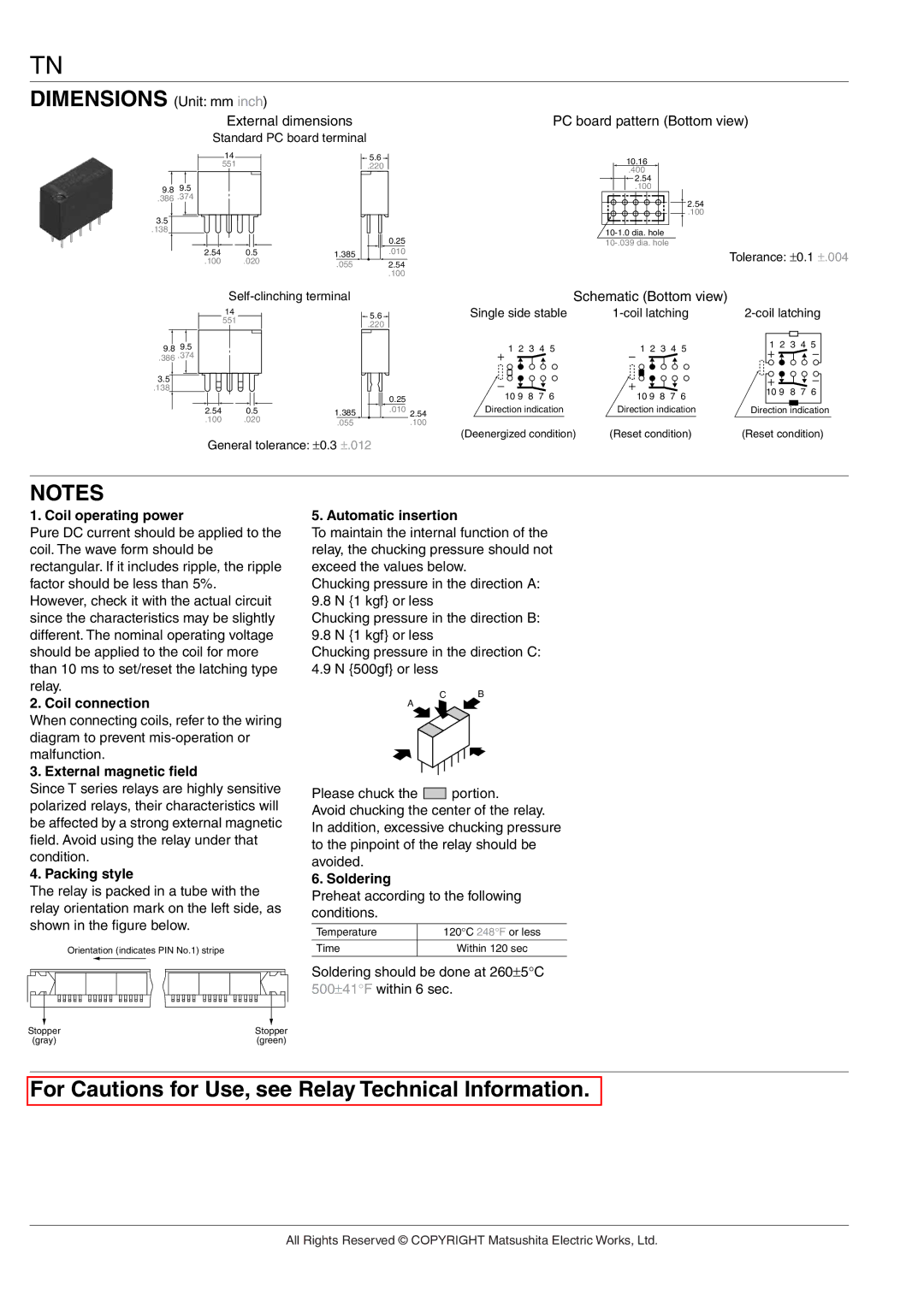
The relay is packed in a tube with the relay orientation mark on the left side, as shown in the figure below.

Orientation (indicates PIN No.1) stripe

5. Automatic insertion

To maintain the internal function of the relay, the chucking pressure should not exceed the values below.

Chucking pressure in the direction A: 9.8 N {1 kgf} or less

Chucking pressure in the direction B: 9.8 N {1 kgf} or less

Chucking pressure in the direction C: 4.9 N {500gf} or less

C B

A

Please chuck the portion.

Avoid chucking the center of the relay. In addition, excessive chucking pressure to the pinpoint of the relay should be avoided.

6. Soldering

Preheat according to the following conditions.

Temperature

120°C 248°F or less


Time

Within 120 sec


Soldering should be done at 260±5°C 500±41°F within 6 sec.

Stopper

Stopper

(gray)

(green)

For Cautions for Use, see Relay Technical Information.

All Rights Reserved © COPYRIGHT Matsushita Electric Works, Ltd.

Page 5
Image 5
Panasonic TN Relay manual Coil operating power, Coil connection, External magnetic field, Packing style, Automatic insertion

TN Relay specifications

The Panasonic TN Relay is a highly regarded electromagnetic relay known for its robust performance and versatility in various applications. This relay is engineered for reliable operation in environments where space is limited yet performance cannot be compromised.

One of the main features of the Panasonic TN Relay is its compact size, which allows for easy integration into tight spaces in electronic devices. Despite its small footprint, it maintains a high switching capacity, making it suitable for a wide range of applications, including automotive systems, industrial equipment, and consumer electronics.

The TN Relay utilizes advanced technologies that enhance its efficiency and reliability. One notable technology is the use of a unique contact material, which ensures excellent conductivity and minimal contact wear over time. This prolongs the relay's life and minimizes maintenance requirements, which is crucial for applications where uptime is essential.

Another important characteristic of the TN Relay is its quick switching capability. The relay is designed to switch quickly between open and closed states, reducing the risk of electromagnetic interference and ensuring smooth operation. This feature is particularly beneficial in high-frequency applications, where precision timing is critical.

In addition to its excellent performance, the Panasonic TN Relay is designed to operate under a wide temperature range, making it suitable for use in various environmental conditions. This feature contributes to its reliability, ensuring that it functions consistently even when exposed to extreme heat or cold.

Additionally, the TN Relay is engineered with safety features to prevent failure and protect connected circuits. It includes built-in safeguards such as overcurrent protection, which helps prevent damage in the event of electrical surges.

Panasonic also places a strong emphasis on environmental responsibility in the manufacturing of the TN Relay. The relay is designed to be RoHS compliant, ensuring that it meets international standards for hazardous substances. This commitment to sustainability makes it an excellent choice for environmentally conscious manufacturers.

In summary, the Panasonic TN Relay stands out due to its compact design, high switching capacity, quick response time, wide operating temperature range, reliability, and safety features. These characteristics make it a preferred choice for various applications where performance and durability are paramount, solidifying its reputation in the relay market.