CONTENTS
Parts and their functions
Front panel
1 |
| 5 |
| 2 |
|
|
|
|
|
| 3 |
|
| 4 | |||
ON | POWER |
|
|
| DVCPRO | DVCPRO 50 |
|
|
|
|
|
|
|
|
|
|
|
|
|
|
|
|
|
|
|
|
|
|
|
|
|
|
|
| |
|
|
|
|
| DV |
|
|
|
|
|
|
|
|
|
|
|
|
OFF |
|
|
|
|
|
|
|
|
|
|
|
|
|
|
|
|
|
METER |
|
|
|
|
| COUNTER ASSEM | VIDEO | CUE | TC | STAND BY PLAYER |
| RECORDER | JOG | SHTL | SLOW | ||
FULL/FINE |
|
|
|
|
|
|
|
|
|
|
|
|
|
|
|
|
|
L |
|
|
|
|
| RESET CH1 | CH2 | CH3 | CH4 |
|
|
|
|
|
|
|
|
MONITOR SELECT |
|
|
|
|
|
|
|
|
| EDIT |
| PLAY |
| REC |
|
|
|
R |
|
|
|
|
| A IN | INSERT | A OUT |
|
|
|
|
|
|
|
| |
|
|
|
|
|
|
|
|
|
|
|
|
|
|
| |||
|
|
|
|
|
|
| TRIM |
|
|
|
|
|
|
|
|
|
|
|
|
|
| PREVIEW/PREVIEW | AUTO EDIT PREROLL |
| SET |
|
| REW |
| STOP |
| FF |
|
|
|
HEADPHONES | MONITOR MIX | INPUT SELECT |
|
|
|
|
|
|
|
|
|
|
| ||||
|
|
|
|
| IN |
| OUT |
|
|
|
|
|
|
|
| ||
|
| VIDEO | AUDIO |
|
|
|
|
|
|
|
|
|
|
|
|
|
|
|
| CH1 | CH2 | CH3 | CH4 | TC |
|
| SUPER | REC INH | INT | TCG | MODE CONTROL |
|
|
| |
| REC LEVEL |
|
|
| UNITY | PRESET MENU SET DIAG | ON | ON | REGEN | TAPE | REMOTE |
|
|
| |||
|
|
|
|
|
|
|
|
|
| PRESET |
|
|
|
|
|
| |
| PB LEVEL |
|
|
| VAR |
|
| OFF | OFF | EXIT |
| EE | LOCAL |
|
|
| |
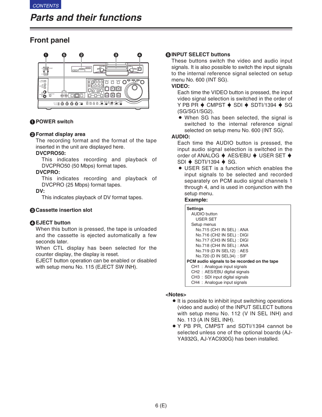
1POWER switch
2Format display area
The recording format and the format of the tape inserted in the unit are displayed here.
DVCPRO50:
This indicates recording and playback of DVCPRO50 (50 Mbps) format tapes.
DVCPRO:
This indicates recording and playback of DVCPRO (25 Mbps) format tapes.
DV:
This indicates playback of DV format tapes.
3Cassette insertion slot
4EJECT button
When this button is pressed, the tape is unloaded and the cassette is ejected automatically a few seconds later.
When CTL display has been selected for the counter display, the display is reset.
EJECT button operation can be enabled or disabled with setup menu No. 115 (EJECT SW INH).
5INPUT SELECT buttons
These buttons switch the video and audio input signals. It is also possible to switch the input signals to the internal reference signal selected on setup menu No. 600 (INT SG).
VIDEO:
Each time the VIDEO button is pressed, the input video signal selection is switched in the order of Y PB PR 5 CMPST 5 SDI 5 SDTI/1394 5 SG (SG/SG1/SG2).
O When SG has been selected, the signal is switched to the internal reference signal selected on setup menu No. 600 (INT SG).
AUDIO:
Each time the AUDIO button is pressed, the input audio signal selection is switched in the order of ANALOG 5 AES/EBU 5 USER SET 5 SDI 5 SDTI/1394 5 SG.
O USER SET is a function which enables the input signals to be selected and recorded separately on PCM audio signal channels 1 through 4, and is used in conjunction with the setup menu.
Example:
Settings
AUDIO button
USER SET
Setup menus
No.715 (CH1 IN SEL) : ANA
No.716 (CH2 IN SEL) : DIGI
No.717 (CH3 IN SEL) : DIGI
No.718 (CH4 IN SEL) : ANA
No.719 (D IN SEL12) : AES
No.720 (D IN SEL34) : SIF
PCM audio signals to be recorded on the tape
CH1 : Analogue input signals
CH2 : AES/EBU digital signals
CH3 : SDI input digital signals
CH4 : Analogue input signals
<Notes>
O It is possible to inhibit input switching operations (video and audio) of the INPUT SELECT buttons with setup menu No. 112 (V IN SEL INH) and No. 113 (A IN SEL INH).
O Y PB PR, CMPST and SDTI/1394 cannot be selected unless one of the optional boards (AJ- YA932G,
6 (E)
