CONTENTS
Setup menus
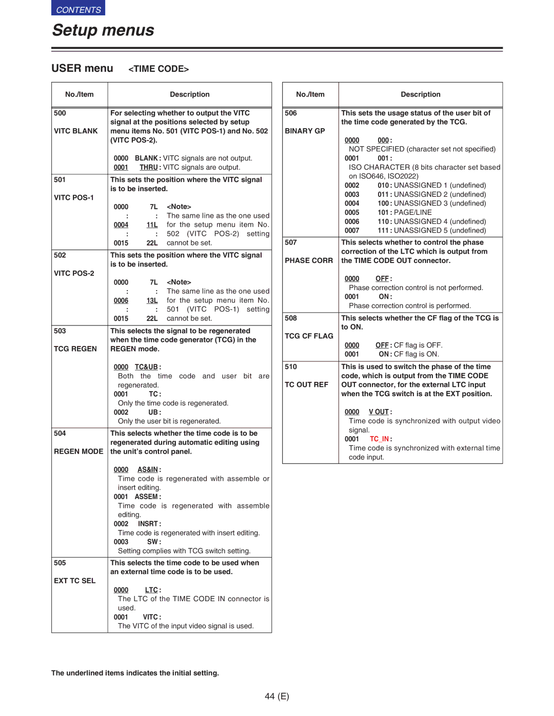
USER menu | <TIME CODE> | ||
|
|
|
|
No./Item |
|
| Description |
|
| ||
|
| ||
500 | For selecting whether to output the VITC | ||
| signal at the positions selected by setup | ||
VITC BLANK | menu items No. 501 (VITC | ||
| (VITC |
| |
| 0000 | BLANK : VITC signals are not output. | |
| 0001 | THRU : VITC signals are output. | |
|
| ||
501 | This sets the position where the VITC signal | ||
| is to be inserted. | ||
VITC |
|
|
|
| 0000 | 7L | <Note> |
| : | : The same line as the one used | |
| 0004 | 11L for the setup menu item No. | |
| : | : | 502 (VITC |
| 0015 | 22L | cannot be set. |
|
| ||
502 | This sets the position where the VITC signal | ||
| is to be inserted. | ||
VITC |
|
|
|
| 0000 | 7L | <Note> |
| : | : The same line as the one used | |
| 0006 | 13L for the setup menu item No. | |
| : | : | 501 (VITC |
| 0015 | 22L | cannot be set. |
|
| ||
503 | This selects the signal to be regenerated | ||
| when the time code generator (TCG) in the | ||
TCG REGEN | REGEN mode. |
| |
| 0000 | TC&UB : |
|
| Both the time code and user bit are | ||
| regenerated. |
| |
| 0001 | TC : |
|
| Only the time code is regenerated. | ||
| 0002 | UB : |
|
| Only the user bit is regenerated. | ||
|
| ||
504 | This selects whether the time code is to be | ||
| regenerated during automatic editing using | ||
REGEN MODE | the unit’s control panel. | ||
| 0000 | AS&IN : |
|
| Time code is regenerated with assemble or | ||
| insert editing. |
| |
| 0001 | ASSEM : |
|
| Time code is regenerated with assemble | ||
| editing. |
| |
| 0002 | INSRT : |
|
| Time code is regenerated with insert editing. | ||
| 0003 | SW : |
|
| Setting complies with TCG switch setting. | ||
|
| ||
505 | This selects the time code to be used when | ||
| an external time code is to be used. | ||
EXT TC SEL |
|
|
|
| 0000 | LTC : |
|
| The LTC of the TIME CODE IN connector is | ||
| used. |
| |
| 0001 | VITC : |
|
| The VITC of the input video signal is used. | ||
|
|
|
|
No./Item |
|
| Description |
|
| ||
|
| ||
506 | This sets the usage status of the user bit of | ||
| the time code generated by the TCG. | ||
BINARY GP |
|
|
|
| 0000 | 000 | : |
| NOT SPECIFIED (character set not specified) | ||
| 0001 | 001 | : |
| ISO CHARACTER (8 bits character set based | ||
| on ISO646, ISO2022) | ||
| 0002 | 010 | : UNASSIGNED 1 (undefined) |
| 0003 | 011 | : UNASSIGNED 2 (undefined) |
| 0004 | 100 | : UNASSIGNED 3 (undefined) |
| 0005 | 101 | : PAGE/LINE |
| 0006 | 110 | : UNASSIGNED 4 (undefined) |
| 0007 | 111 | : UNASSIGNED 5 (undefined) |
|
| ||
507 | This selects whether to control the phase | ||
| correction of the LTC which is output from | ||
PHASE CORR | the TIME CODE OUT connector. | ||
| 0000 | OFF : | |
| Phase correction control is not performed. | ||
| 0001 | ON : | |
| Phase correction control is performed. | ||
|
| ||
508 | This selects whether the CF flag of the TCG is | ||
| to ON. |
|
|
TCG CF FLAG |
|
|
|
| 0000 | OFF : CF flag is OFF. | |
| 0001 | ON : CF flag is ON. | |
|
| ||
510 | This is used to switch the phase of the time | ||
| code, which is output from the TIME CODE | ||
TC OUT REF | OUT connector, for the external LTC input | ||
| when the TCG switch is at the EXT position. | ||
| 0000 | V OUT : | |
| Time code is synchronized with output video | ||
| signal. |
| |
| 0001 | TC_IN : | |
| Time code is synchronized with external time | ||
| code input. |
| |
|
|
|
|
The underlined items indicates the initial setting.
44 (E)