Installation of Auto Iris Lens Connector
Install the lens connector (YFE4191J100) when using a video drive ALC lens.
The installation should be made by qualified ser- vice personnel or system installers.
(1)Cut the iris control cable at the edge of the lens connector to remove the existing lens connector and then remove the outer cable cover as shown in the diagram below.
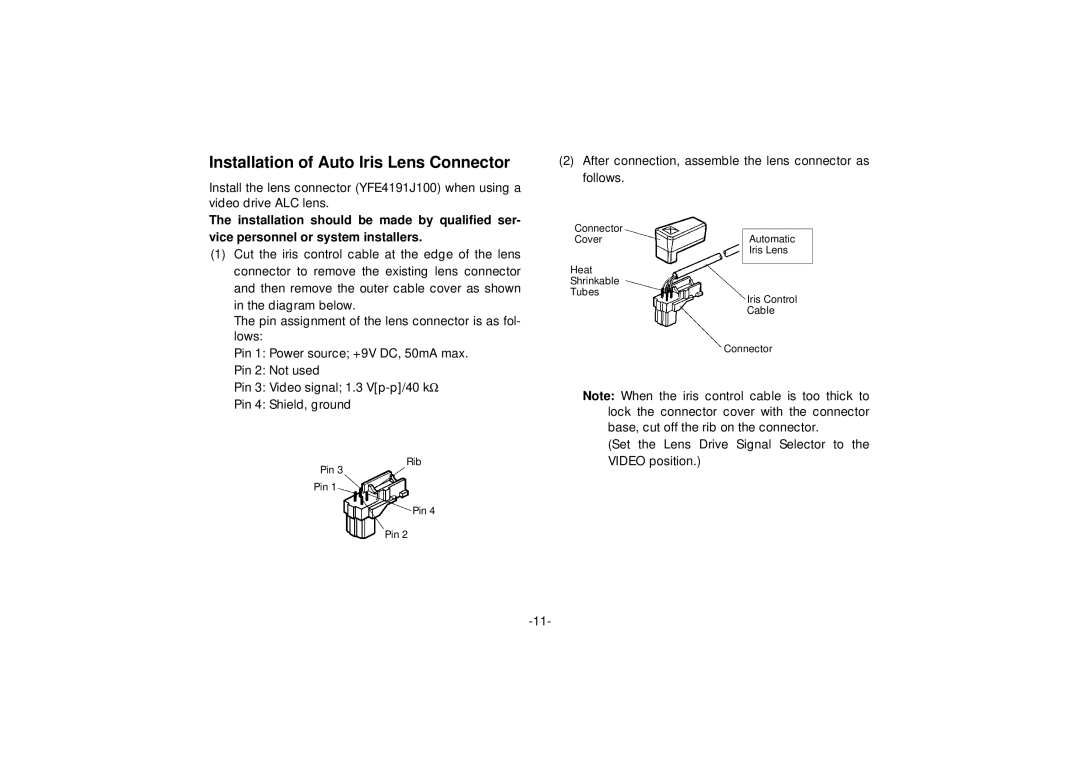
The pin assignment of the lens connector is as fol- lows:
Pin 1: Power source; +9V DC, 50mA max.
Pin 2: Not used
Pin 3: Video signal; 1.3
Pin 4: Shield, ground
Rib
Pin 3
Pin 1
Pin 4
Pin 2
(2)After connection, assemble the lens connector as follows.
Connector
CoverAutomatic
Iris Lens
Heat
Shrinkable
Tubes
Iris Control
Cable
Connector
Note: When the iris control cable is too thick to lock the connector cover with the connector base, cut off the rib on the connector.
(Set the Lens Drive Signal Selector to the VIDEO position.)