| • | 2 |
• | MAIN UNIT AND |
MAIN UNIT AND ACCESSORIES- ASSEMBLY INSTRUCTIONS
STAND A~SORIES |
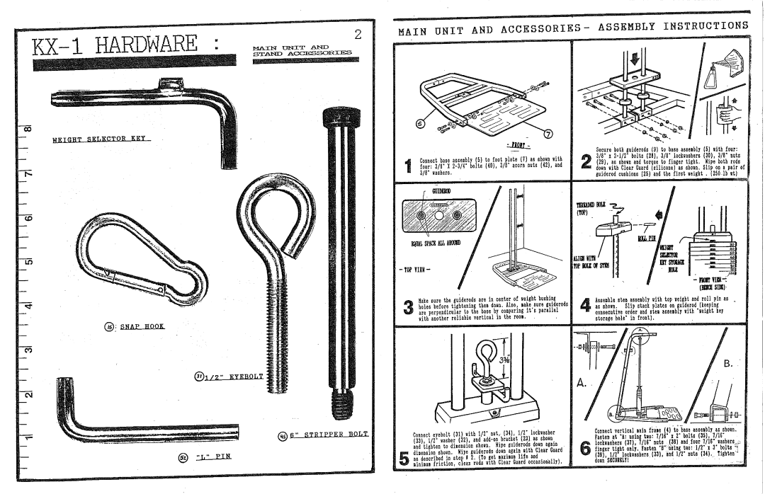
WEIGHT SELECTOR KEY
®: SNAP HOOK
@h /2" EYEBOLT
..... |
| @6" STRIPPER BOW |
|
® .. I, Of PIN
- lROlT -
Connect base assenbly (5) to foot plate (7) as shown with
1 four: 3/S"
-TOP YUW-
Hake sure the guiderods are in center of weight bushing
3 holes before tigbtening tben down. Also, nake sure guiderods are perpendicular to the base by conparing it's parallel with another reliable vertical in the roon.
Connect eyebolt (31) with l/Z" nut, (31), 1/2" lonimber (33), 1/2' washer (3Z), and
and tigbten to diBension shown. Hipe guiderods down again - dinension sbown. Hipe guiderods down again with Clear Guard
5 as described in step I 2. 110 get Balilu, life and lininuB friction, clean rods with Clear Guard occasionally).
k~
-llf;
Sec~re both !uiderods (9) to base asselbly (5) with four: 3/S I
2 (Z9), ~s sbown and torque to finger tight. Nip~ both rods do~n wlth Clear Guard (silicone) as shown. Slip on a pair of gUlderod cusbions (Z5) and the !irst weight.
n
(I
.0
c
C
6C
~
- nm
(m SIll)'
Asseable sten assenbly with top weigbt and roll pin as
4 as shown. Slip staok plates on guiderod (keeping consecutive order and sten assenbly with "weight key storage hole" in front).
A. -
Connect vertical lain
6 | flnger ti!bt only. rasten Tusing tlO: 1/2" I 3" bolts ;; | |||||
(39), | 1/2 lonimbers | (33), and liZ" nuta (34). |
| |||
| dOln | mOBEL1! | - | - | "." | |
