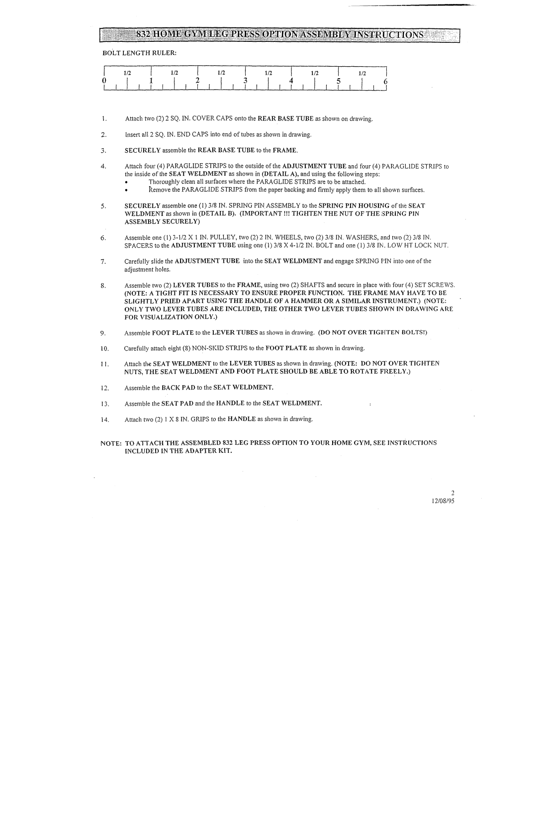
BOLT LENGTH RULER: |
|
|
|
|
|
|
|
|
|
| ||
1/2 | I | 1/2 | I | 1/2 | I | 1/2 | I |
| 1/2 | I | 1/2 | ~ |
| 1 | I , | 2 | I . 1 | 3 | , ..I | 4 | , |
| 5 | , | __1 |
|
| , | I , | , , |
| I , I | ||||||
Attach two (2) 2 SQ. IN, COVERCAPSonto the REARBASETUBEas shown on drawing.
2.Insert all 2 SQ.IN. ENDCAPSinto end of tubes as shownin drawing.
3.SECURELYassemble the REARBASETUBE to the FRAME.
4.Attach four (4) PARAGLIDESTRIPSto the outside of the ADJUSTMENTTUBEand tour (4) PARAGLIDESTRIPS the inside of the SEATWELDMENTas shown in (DETAILA), and using the following steps:
¯Thoroughlyclean all surfaces where the PARAGLIDESTRIPSare to be attached.
¯kemovethe PARAGLIDESTRIPSfrom the paper backing and firmly apply them to all shown surfaces.
SECURELYassemble one (1) 3/8 IN. SPRINGPIN.ASSEMBLYto the SPRINGPIN HOUSINGof tl~e SEAT WELDMENTas shown in (DETAIL B). (IMPORTANT!!! TIGHTENTHE NUT OF THE SPRING ASSEMBLY SECURELY)
Assembleone
Carefully slide the ADJUSTMENTTUBEinto the SEATWELDMENTand engage SPRINGPIN into one of the adjustmentholes.
Assemble two (2) LEVERTUBESto the FRAME,using two (2) SHAFTSand secure in place with four (4) SET SCREWS. (NOTE: A TIGHT FIT IS NECESSARYTO ENSURE PROPER FUNCTION. THE FRAMEMAYHAVE TO BE SLIGHTLY PRIED APART USING THE HANDLEOF A HAMMEROR A SIMILAR INSTRUMENT.) (NOTE: ONLY TWO LEVER TUBES ARE INCLUDED, THE OTHER TWO LEVER TUBES SHO'WN IN DRAWINGARE FOR VISUALIZATION ONLY.)
Assemble FOOTPLATE to the LEVERTUBESas shown in drawing. (DO NOTOVERTIGHTENBOLTS!)
10.Carefully attach eight (8)
I1. Attach the SEAT WELDMENTto the LEVERTUBESas shown in drawing. (NOTE: DONOTOVERTIGHTEN NUTS, THE SEAT WELDMENTAND FOOT PLATE SHOULD BE ABLE TO ROTATE FREELY.)
12.Assemble the BACKPAD to the SEAT WELDMENT.
13.Assemble the SEATPAD and the HANDLEto the SEAT WELDMENT.
14.Attach two (2) I X 8 IN. GRIPSto the HANDLEas shownin drawing.
NOTE: TO ATTACH THE ASSEMBLED832 LEG PRESS OPTION TO YOUR HOMEGYM, SEE INSTRUCTIONS INCLUDED IN THE ADAPTERKIT.
2
12/08/95