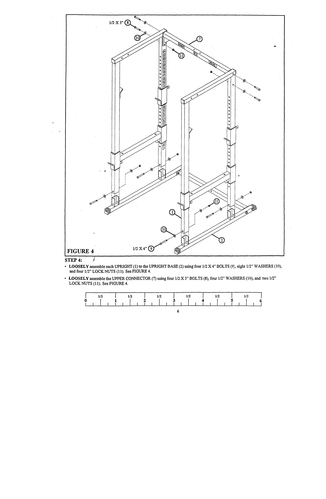
FIGURE 4
STEP4:
¯LOOSELYassemble each UPRIGHT(1) to the UPRIGHTBASE(2) using four 1/2 X 4" BOLTS(91, eight 1/2" WASHERS and four 1/2" LOCKNUTS(1 1). See FIGURE
¯LOOSELYassemble the UPPERCONNECTOP,(7) using four 1/2 3"BOLTS (8), fou r 1/2 " WASHEP, S (10), and two LOCKNUTS(11). See FIGURE
456 I
6
