| POWER RACK |
|
|
|
| 1 |
|
|
| 1/2 X 3” | 24 |
| 26 | 25 |
|
|
|
| |
| 8 |
|
|
|
| 20 21 |
|
| 20 |
|
|
3/8 X | 19 |
|
|
| 5 |
|
|
FIGURE 2 |
|
|
|
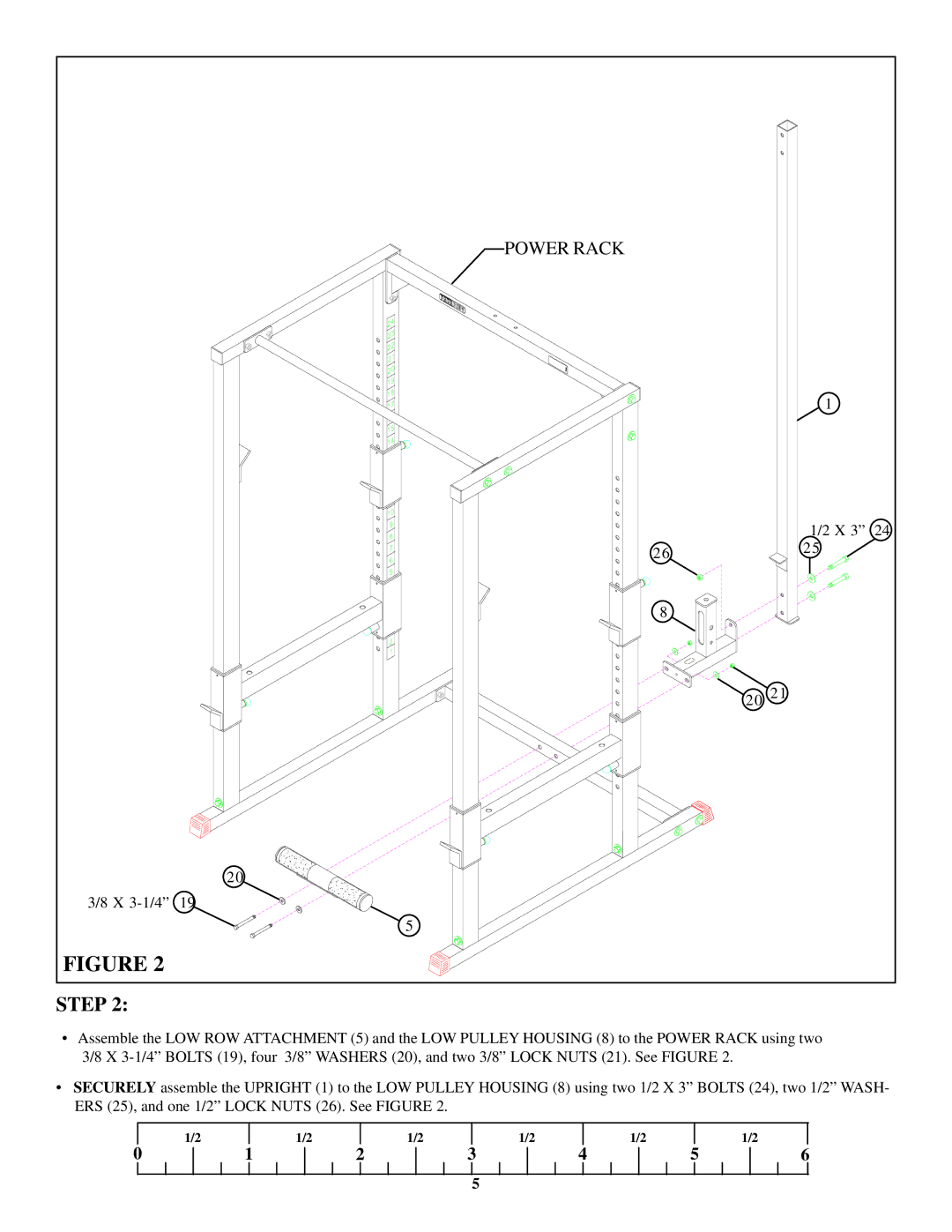
STEP 2:
•Assemble the LOW ROW ATTACHMENT (5) and the LOW PULLEY HOUSING (8) to the POWER RACK using two 3/8 X
•SECURELY assemble the UPRIGHT (1) to the LOW PULLEY HOUSING (8) using two 1/2 X 3” BOLTS (24), two 1/2” WASH- ERS (25), and one 1/2” LOCK NUTS (26). See FIGURE 2.
| 1/2 |
| 1/2 |
| 1/2 |
| 1/2 |
| 1/2 |
|
| 1/2 |
0 | 1 | 2 | 3 | 4 | 5 | 6 | ||||||
5