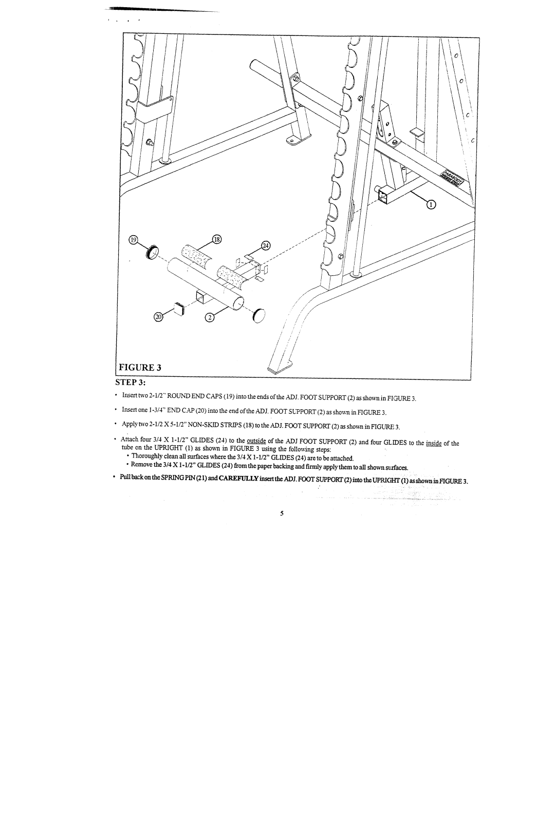
FIGURE
STEP3:
¯Insert two 2-1/2' ROUNDENDCAPS(19) into the ends of the .ADJ. FOOTSUPPORT(2) as shownin FIGURE
¯Insert one I-3/4" ENiDCAP(20) into the end ofthe ADJ. FOOTSUPPORT(2) as shownin FIGURE
¯Apply m'o 2-1/2 X 5-1/2" NON-SKIDSTRIPS(18) to the ADJ. FOOTSUPPOKI"(2) as sho~n in FIGL~q.E
¯Attach four 3/4 X 1-I/2" GLIDES(24) to the outside of the .4~DJ FOOTSUPPORT(2) and four GLIDESto the inside of the tube on the UPRIGHT(1) as showrt in FIGURE3 using the follo~ng steps:
¯Thoroughlyclean all surfaces wherethe 3/4 X1-112" GLIDES(24) are to be attached.
¯Removethe 3/4 XI o 1/2" GLIDES(24) fromthe paper backingand firmly apply themto all show~lsrxfaees.
¯Pull back on the SPRINGPIN(21 ) and CAREFIILLYinsert the ADI. FOOTSUPPOKr(2) into the UPRIGHT(1) as shownin FIGURE3.

