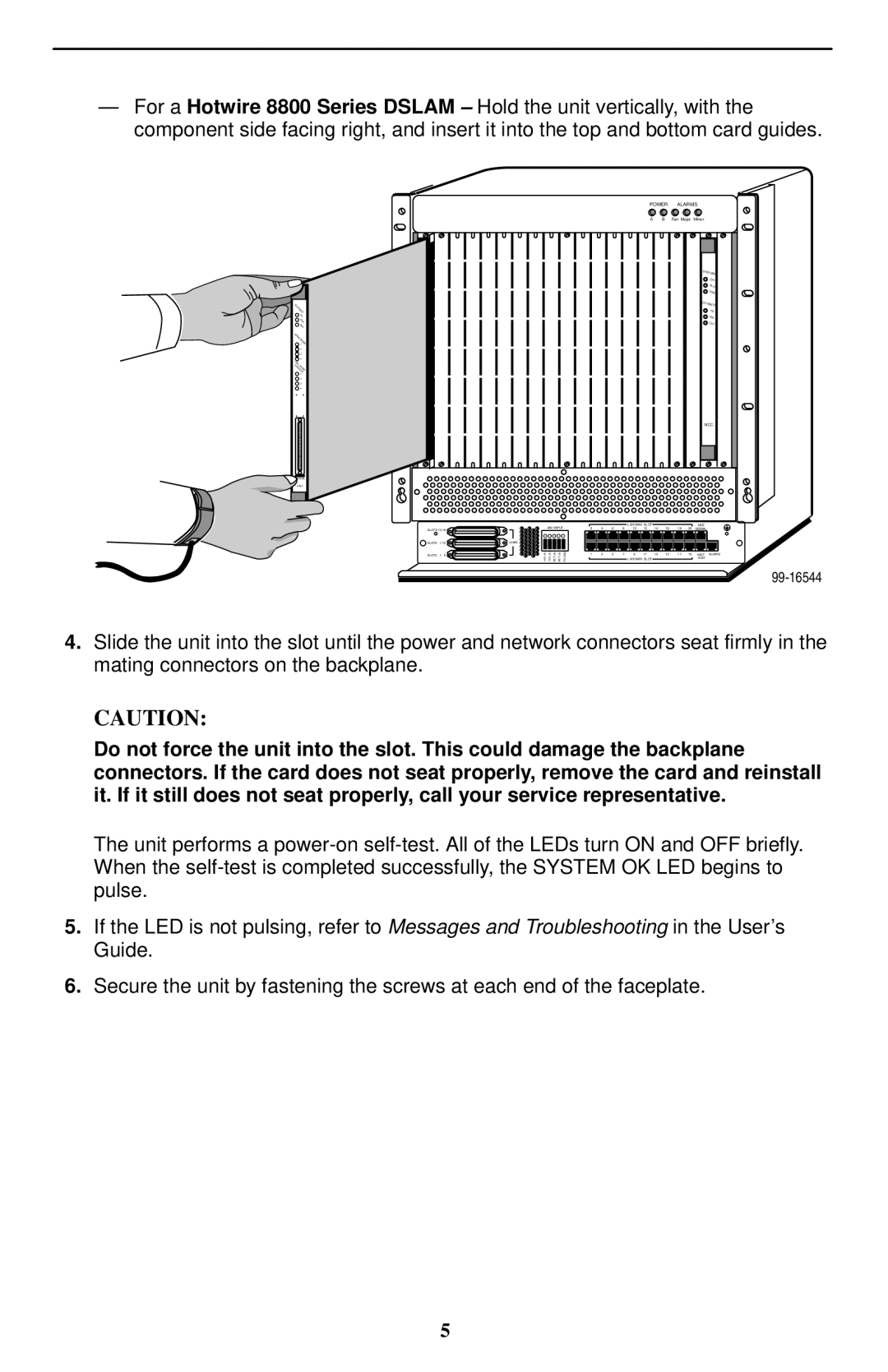
—For a Hotwire 8800 Series DSLAM – Hold the unit vertically, with the component side facing right, and insert it into the top and bottom card guides.
POWER ALARMS
A | B Fan Major Minor |
|
|
|
|
|
|
|
|
|
|
|
|
|
|
|
| SYSTEM | |
|
|
|
|
|
|
|
|
|
|
|
|
|
|
|
|
| OK |
|
|
|
|
|
|
|
|
|
|
|
|
|
|
|
|
| Alm |
|
|
|
|
|
|
|
|
|
|
|
|
|
|
|
|
| Test |
SYSTEM |
|
|
|
|
|
|
|
|
|
|
|
|
|
|
| ETHERNET | |
|
|
|
|
|
|
|
|
|
|
|
|
|
|
|
| TX | |
OK |
|
|
|
|
|
|
|
|
|
|
|
|
|
|
|
| RX |
Alrm |
|
|
|
|
|
|
|
|
|
|
|
|
|
|
|
| Coll |
Test |
|
|
|
|
|
|
|
|
|
|
|
|
|
|
|
|
|
SYNC |
|
|
|
|
|
|
|
|
|
|
|
|
|
|
|
|
|
PORT1 |
|
|
|
|
|
|
|
|
|
|
|
|
|
|
|
|
|
2 |
|
|
|
|
|
|
|
|
|
|
|
|
|
|
|
|
|
3 |
|
|
|
|
|
|
|
|
|
|
|
|
|
|
|
|
|
4 |
|
|
|
|
|
|
|
|
|
|
|
|
|
|
|
|
|
DSL |
|
|
|
|
|
|
|
|
|
|
|
|
|
|
|
|
|
LINKPORT- |
|
|
|
|
|
|
|
|
|
|
|
|
|
|
|
|
|
UP1 |
|
|
|
|
|
|
|
|
|
|
|
|
|
|
|
|
|
2 |
|
|
|
|
|
|
|
|
|
|
|
|
|
|
|
|
|
3 |
|
|
|
|
|
|
|
|
|
|
|
|
|
|
|
|
|
4 |
|
|
|
|
|
|
|
|
|
|
|
|
|
|
|
|
|
|
|
|
|
|
|
|
|
|
|
|
|
|
|
|
| MCC | |
M/HDSL |
|
|
|
|
|
|
|
|
|
|
|
|
|
|
|
|
|
8785 |
|
|
|
|
|
|
|
|
|
|
|
|
|
|
|
|
|
|
|
|
|
|
|
|
|
| LAN/WAN SLOT |
| 16 |
| 20 | MGT |
| ||
SLOTS |
|
|
| 2 | 4 | 6 | 8 | 10 | 12 | 14 | 18 | SERIAL |
| ||||
SLOTS | LINES |
|
| GNDFR |
|
|
|
|
|
|
|
|
|
|
|
| |
|
|
| 48V- (A) | 48V- (B) RET(A) RET(B) |
|
|
|
| LAN/WAN SLOT |
|
|
|
| 10BT |
| ||
SLOTS | 1 - 6 | A | B |
|
| 1 | 3 | 5 | 7 | 9 | 11 | 13 | 15 | 17 | 19 | MGT | ALARM |
99-16544
4.Slide the unit into the slot until the power and network connectors seat firmly in the mating connectors on the backplane.
CAUTION:
Do not force the unit into the slot. This could damage the backplane connectors. If the card does not seat properly, remove the card and reinstall it. If it still does not seat properly, call your service representative.
The unit performs a
5.If the LED is not pulsing, refer to Messages and Troubleshooting in the User’s Guide.
6.Secure the unit by fastening the screws at each end of the faceplate.
5