3.0 INSTALLATION
Patton’s Model 1000RP Series power supply modules are easy to install and require no configuration. This section describes the functions of the Model 1000R16P rack chassis, tells how to install front and rear power supply cards into the chassis and how to make the power interface connections.
3.1 THE MODEL 1000R16P RACK CHASSIS
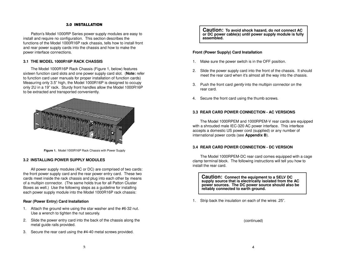
The Model 1000R16P Rack Chassis (Figure 1, below) features sixteen function card slots and one power supply card slot. (Note: refer to function card user manuals for proper installation of function cards) Measuring only 3.5” high, the Model 1000R16P is designed to occupy only 2U in a 19” rack. Sturdy front handles allow the Model 1000R16P to be extracted and transported conveniently.
Figure 1. Model 1000R16P Rack Chassis with Power Supply
3.2 INSTALLING POWER SUPPLY MODULES
All power supply modules (AC or DC) are comprised of two cards: the front power supply card and the rear power entry card. These two cards meet inside the rack chassis and plug into each other by means of a multipin connector. (The same holds true for all Patton Cluster Boxes as well.) Use the following steps as a guideline for installing each power supply module into the Model 1000R16P rack chassis:
Rear (Power Entry) Card Installation
1.Attach the ground wire using the star washer and the
2.Slide the power entry card into the back of the chassis along the metal guide rails provided.
3.Secure the rear card using the
Caution: To avoid shock hazard, do not connect AC or DC power cable(s) until power supply module is fully assembled.
Front (Power Supply) Card Installation
1.Make sure the power switch is in the OFF position.
2.Slide the power supply card into the front of the chassis. It should meet the rear card when it's almost all the way into the chassis.
3.Push the front card gently into the multipin connector on the rear card.
4.Secure the front card using the thumb screws.
3.3 REAR CARD POWER CONNECTION - AC VERSIONS
The Model 1000RPEM and
3.4 REAR CARD POWER CONNECTION - DC VERSION
The Model
Caution: Connect the equipment to a SELV DC supply source that is electrically isolated from the AC power sources. The DC power source should also be reliably connected to earth ground.
1.Strip back the insulation on each of the wires .25”.
(continued)
3 | 4 |