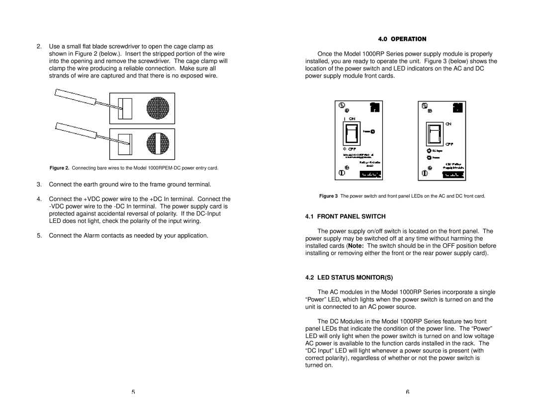
2.Use a small flat blade screwdriver to open the cage clamp as shown in Figure 2 (below.). Insert the stripped portion of the wire into the opening and remove the screwdriver. The cage clamp will clamp the wire producing a reliable connection. Make sure all strands of wire are captured and that there is no exposed wire.
Figure 2. Connecting bare wires to the Model 1000RPEM-DC power entry card.
3.Connect the earth ground wire to the frame ground terminal.
4.Connect the +VDC power wire to the +DC In terminal. Connect the
5.Connect the Alarm contacts as needed by your application.
4.0 OPERATION
Once the Model 1000RP Series power supply module is properly installed, you are ready to operate the unit. Figure 3 (below) shows the location of the power switch and LED indicators on the AC and DC power supply module front cards.
Figure 3 The power switch and front panel LEDs on the AC and DC front card.
4.1 FRONT PANEL SWITCH
The power supply on/off switch is located on the front panel. The power supply may be switched off at any time without harming the installed cards (Note: The switch should be in the OFF position before installing or removing either the front or the rear power supply card).
4.2 LED STATUS MONITOR(S)
The AC modules in the Model 1000RP Series incorporate a single “Power” LED, which lights when the power switch is turned on and the unit is connected to an AC power source.
The DC Modules in the Model 1000RP Series feature two front panel LEDs that indicate the condition of the power line. The “Power” LED will only light when the power switch is turned on and low voltage AC power is available to the function cards installed in the rack. The “DC Input” LED will light whenever a power source is present (with correct polarity), regardless of whether or not the power switch is turned on.
5 | 6 |