Switching the Power Supply On and Off
The power supply on/off switch is located on the front panel. When plugged in and switched on, the power LED will glow. Since the Model 1000R16 is “hot swappable”,you do not need to turn off the power before removing rack cards. The power supply may be switched off at any time without harming the installed cards.
NOTE: Please refer to the Model 1000RP Series User Manual AC and DC Rack Mount Power Supplies for fuse and power card replacement information.
4.2 INSTALLING THE MODEL 1012ARC INTO THE CHASSIS
The Model 1012ARC is comprised of a front card and a rear card. The two cards meet inside the rack chassis and plug into each other via mating 50 pin card edge connectors. Use the following steps to install each Model 1012ARC into the Model 1000R16 rack chassis:
1.Slide the rear card into the back of the chassis along the metal rails.
2.Secure the rear card using the metal screws provided.
3.Slide the card into the front of the chassis. It should meet the rear card when it is almost in the chassis.
4.Push the front card gently into the
5.Secure the front card using the thumb screws.
NOTE: Since the Model 1000R16 chassis allows “hot swapping” of cards, it is not necessary to turn the power off when you install or remove a Model 1012ARC.
4.3 TERMINAL INTERFACE CONNECTION
The
The Model 1012ARC is wired as a DCE (Data
(301)
9
4.4 TWISTED PAIR CONNECTION
The Model 1012ARC operates over two twisted pair. In all applications, the twisted pair wire must be 26 AWG or thicker, unconditioned, dry metallic wire. Both shielded and unshielded wire yield favorable results. Note: The Model 1012ARC can only communicate in a closed data circuit with another Model 1012ARC.
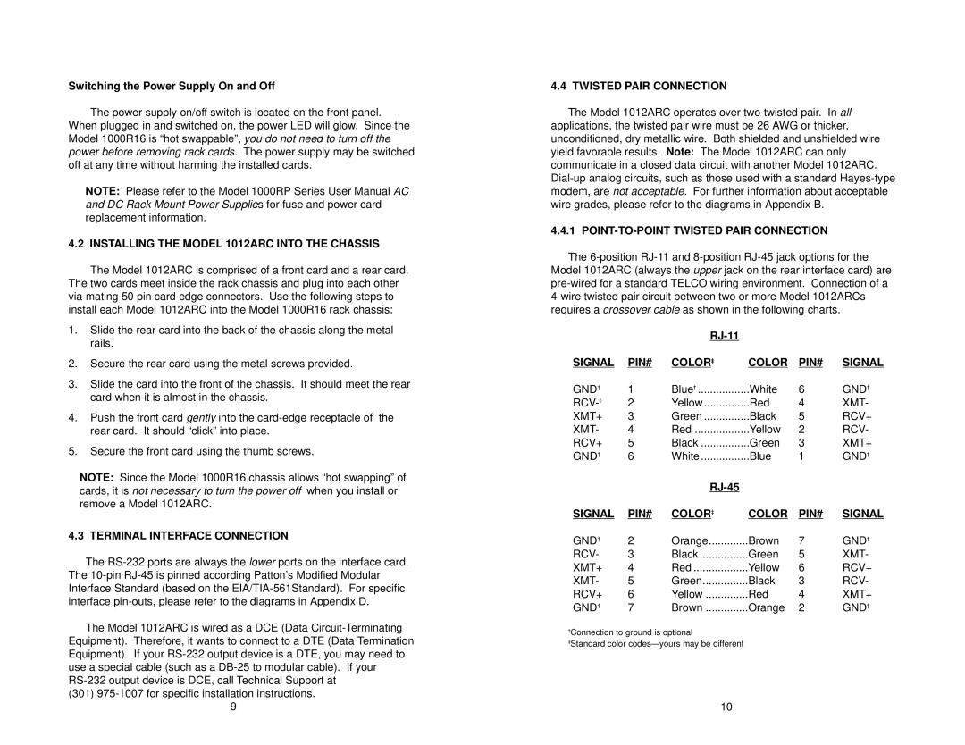
4.4.1 POINT-TO-POINT TWISTED PAIR CONNECTION
The
|
|
|
|
| |
SIGNAL | PIN# | COLOR‡ | COLOR | PIN# | SIGNAL |
GND† | 1 | Blue‡ | White | 6 | GND† |
2 | Yellow | Red | 4 | XMT- | |
XMT+ | 3 | Green | Black | 5 | RCV+ |
XMT- | 4 | Red | Yellow | 2 | RCV- |
RCV+ | 5 | Black | Green | 3 | XMT+ |
GND† | 6 | White | Blue | 1 | GND† |
|
|
|
|
| |
SIGNAL | PIN# | COLOR‡ | COLOR | PIN# | SIGNAL |
GND† | 2 | Orange | Brown | 7 | GND† |
RCV- | 3 | Black | Green | 5 | XMT- |
XMT+ | 4 | Red | Yellow | 6 | RCV+ |
XMT- | 5 | Green | Black | 3 | RCV- |
RCV+ | 6 | Yellow | Red | 4 | XMT+ |
GND† | 7 | Brown | Orange | 2 | GND† |
†Connection to ground is optional
‡Standard color
10