| 1 |
| 1 |
|
| ||
|
| 2 | |
| 2 |
| 3 |
| 3 |
| 4 |
| 4 |
| 5 |
| 5 |
| 6 |
| 6 |
| 7 |
|
|
| 8 |
|
|
| |
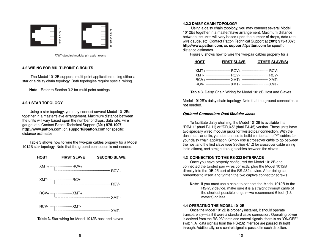
AT&T standard modular pin assignments |
| ||
4.2 WIRING FOR MULTI-POINT CIRCUITS
The Model 1012B supports
Note: Refer to Section 3.2 for
4.2.1 STAR TOPOLOGY
Using a star topology, you may connect several Model 1012Bs together in a master/slave arrangement. Maximum distance between the units will vary based upon the number of drops, data rate, wire gauge, etc. Contact Patton Technical Support (301)
Table 3 shows how to wire the
HOST | FIRST SLAVE | SECOND SLAVE |
XMT+RCV+
RCV+
XMT-RCV-
RCV-
RCV+XMT+
XMT+
RCV-XMT-
XMT-
Table 3. Star wiring for Model 1012B host and slaves
9
4.2.2 DAISY CHAIN TOPOLOGY
Using a daisy chain topology, you may connect several Model 1012Bs together in a master/slave arrangement. Maximum distance between the units will vary based upon the number of drops, data rate, wire gauge, etc. Contact Patton Technical Support at (301)
Figure 6 shows how to wire the two-pair cables properly for a
HOST | FIRST SLAVE | OTHER SLAVE(S) |
XMT+ | RCV+ | RCV+ |
XMT- | RCV- | RCV- |
RCV+ | XMT+ | XMT+ |
RCV- | XMT- | XMT- |
Table 3. Daisy Chain Wiring for Model 1012B Host and Slaves
Model 1012B’s daisy chain topology. Note that the ground connection is not needed.
Optional Connection: Dual Modular Jacks
To facilitate daisy chaining, the Model 1012B is available in a "DRJ11" (dual
4.3CONNECTION TO THE RS-232 INTERFACE
Once you have properly configured the Model 1012B and
connected the twisted pair wires correctly, plug the Model 1012B directly into the
Note: If you must use a cable to connect the Model 1012B to the
4.4 OPERATING THE MODEL 1012B
Once the Model 1012B is properly installed, it should operate
10