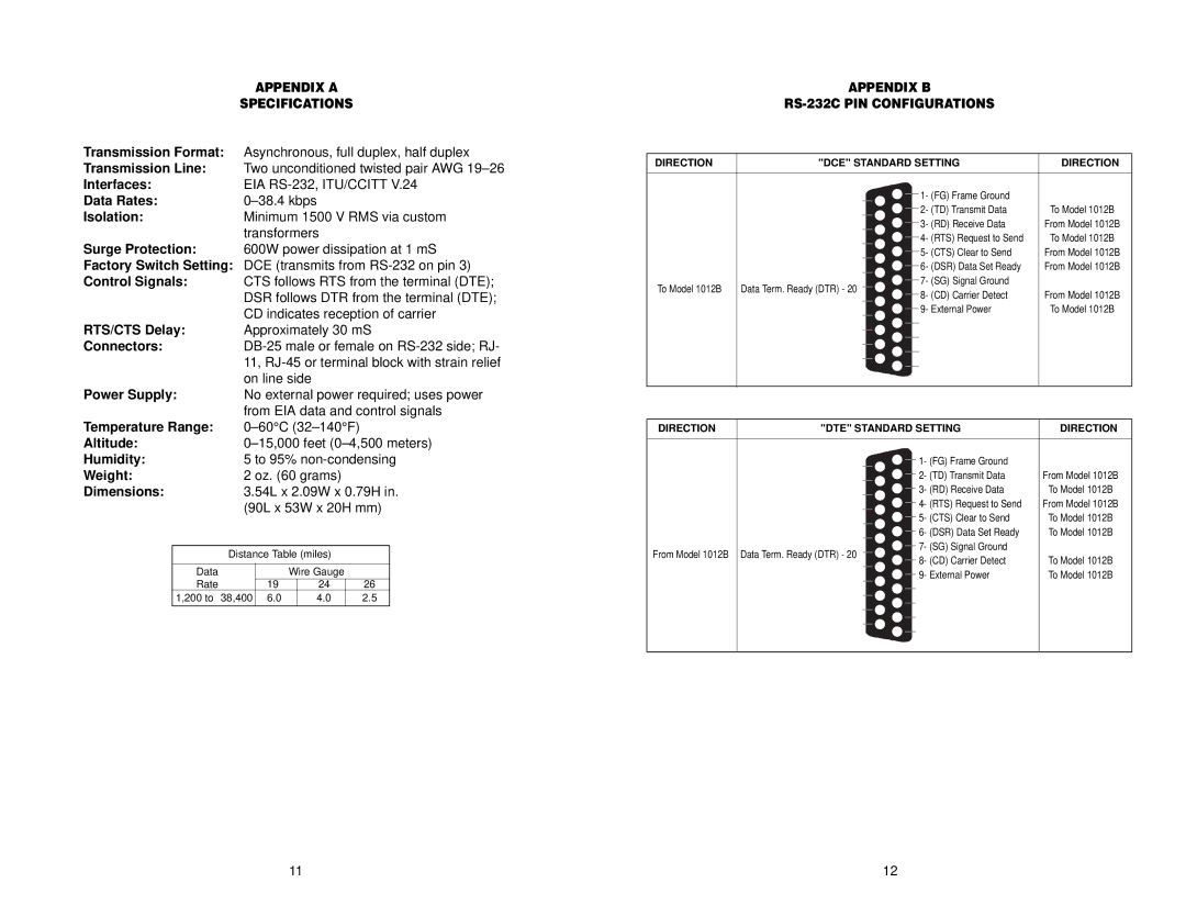
|
| APPENDIX A |
|
| ||||
|
| SPECIFICATIONS |
|
| ||||
Transmission Format: | Asynchronous, full duplex, half duplex | |||||||
Transmission Line: | Two unconditioned twisted pair AWG | |||||||
Interfaces: | EIA | |||||||
Data Rates: |
|
| ||||||
Isolation: | Minimum 1500 V RMS via custom | |||||||
|
| transformers |
|
| ||||
Surge Protection: | 600W power dissipation at 1 mS | |||||||
Factory Switch Setting: | DCE (transmits from | |||||||
Control Signals: | CTS follows RTS from the terminal (DTE); | |||||||
|
| DSR follows DTR from the terminal (DTE); | ||||||
|
| CD indicates reception of carrier | ||||||
RTS/CTS Delay: | Approximately 30 mS | |||||||
Connectors: | ||||||||
|
| 11, | ||||||
|
| on line side |
|
| ||||
Power Supply: | No external power required; uses power | |||||||
|
| from EIA data and control signals | ||||||
Temperature Range: |
|
| ||||||
Altitude: | ||||||||
Humidity: | 5 to 95% | |||||||
Weight: | 2 oz. (60 grams) |
|
| |||||
Dimensions: | 3.54L x 2.09W x 0.79H in. | |||||||
|
| (90L x 53W x 20H mm) | ||||||
|
|
|
|
|
|
| ||
| Distance Table (miles) |
|
| |||||
|
|
|
|
|
|
|
|
|
| Data |
|
| Wire Gauge |
|
| ||
| Rate |
|
|
|
|
|
|
|
|
| 19 |
| 24 |
| 26 |
| |
| 1,200 to 38,400 | 6.0 |
| 4.0 |
| 2.5 |
| |
APPENDIX B
RS-232C PIN CONFIGURATIONS
DIRECTION | "DCE" STANDARD SETTING | DIRECTION | ||||
|
|
|
|
|
| |
|
|
|
|
|
|
|
|
|
|
| 1 | - (FG) Frame Ground |
|
|
|
|
| |||
|
|
|
| 2 | - (TD) Transmit Data | To Model 1012B |
|
|
| ||||
|
|
|
| 3 | - (RD) Receive Data | From Model 1012B |
|
|
| ||||
|
|
|
| 4 | - (RTS) Request to Send | To Model 1012B |
|
|
| ||||
|
|
|
| 5 | - (CTS) Clear to Send | From Model 1012B |
|
|
| ||||
|
|
|
| 6 | - (DSR) Data Set Ready | From Model 1012B |
|
|
| ||||
To Model 1012B | Data Term. Ready (DTR) - 20 |
|
| 7 | - (SG) Signal Ground |
|
|
| |||||
|
| 8 | - (CD) Carrier Detect | From Model 1012B | ||
|
|
|
| |||
|
|
|
| 9 | - External Power | To Model 1012B |
|
|
| ||||
|
|
|
|
|
|
|
|
|
|
|
|
|
|
|
|
|
|
|
|
|
|
|
|
|
|
|
|
|
|
|
|
|
|
|
|
|
|
|
|
|
|
DIRECTION | "DTE" STANDARD SETTING | DIRECTION | ||
|
|
|
|
|
|
|
| 1- (FG) Frame Ground |
|
|
|
|
| |
|
|
| 2- (TD) Transmit Data | From Model 1012B |
|
|
| 3- (RD) Receive Data | To Model 1012B |
|
|
| 4- (RTS) Request to Send | From Model 1012B |
|
|
| 5- (CTS) Clear to Send | To Model 1012B |
|
|
| 6- (DSR) Data Set Ready | To Model 1012B |
From Model 1012B | Data Term. Ready (DTR) - 20 |
| 7- (SG) Signal Ground |
|
| 8- (CD) Carrier Detect | To Model 1012B | ||
|
|
| ||
|
|
| 9- External Power | To Model 1012B |
|
|
|
|
|
|
|
|
|
|
11 | 12 |
