3.0 CONFIGURATION
By default, the Model 1012B is configured to be a DCE with the transmitter set for controlled carrier. If the 1012B is in controlled carrier mode for
The DTE/DCE slide switch (SW1 in Figure 1) is used to configure DTE or DCE orientation. The RTS/CD control jumper (J2 in Figure 1) is used to configure constant/controlled carrier mode.
Section 3.1 describes how to configure the DTE/DCE switch. Section 3.2 provides information on configuring the transmitter to be constant or controlled.
3.1 SETTING THE MODEL 1012B AS DCE OR DTE
Note: Remember that when the DTE/DCE switch is set for DCE, the 1012B functions as a DCE device. Otherwise, when the switch is in the DTE position, the short range modem operates as a DTE device..
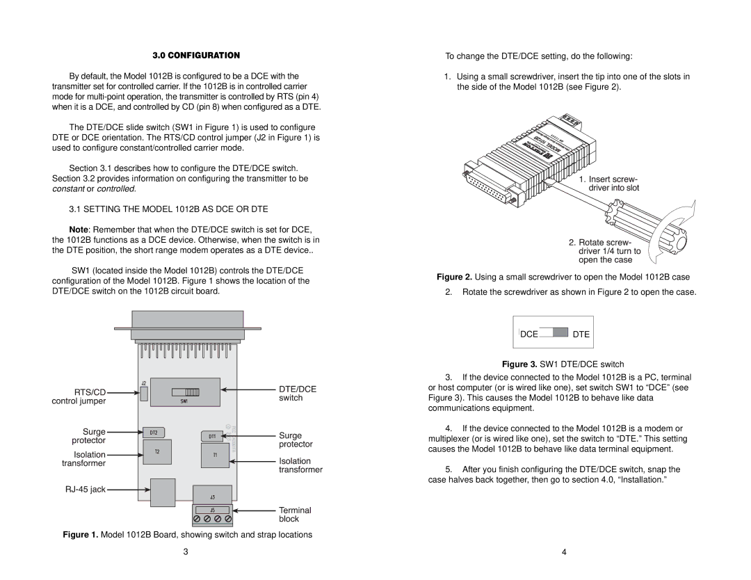
SW1 (located inside the Model 1012B) controls the DTE/DCE configuration of the Model 1012B. Figure 1 shows the location of the DTE/DCE switch on the 1012B circuit board.
Figure 1. Model 1012B Board, showing switch and strap locations
3
To change the DTE/DCE setting, do the following:
1.Using a small screwdriver, insert the tip into one of the slots in the side of the Model 1012B (see Figure 2).
Figure 2. Using a small screwdriver to open the Model 1012B case
2.Rotate the screwdriver as shown in Figure 2 to open the case.
DCE  DTE
DTE
Figure 3. SW1 DTE/DCE switch
3.If the device connected to the Model 1012B is a PC, terminal or host computer (or is wired like one), set switch SW1 to “DCE” (see Figure 3). This causes the Model 1012B to behave like data communications equipment.
4.If the device connected to the Model 1012B is a modem or multiplexer (or is wired like one), set the switch to “DTE.” This setting causes the Model 1012B to behave like data terminal equipment.
5.After you finish configuring the DTE/DCE switch, snap the case halves back together, then go to section 4.0, “Installation.”
4