2.Secure the rear card using the supplied metal screws.
3.Slide the front card into the chassis until you feel resistance as the front card engages the rear card. When that happens, gently push the front card forward until it is fully seated in the
4.Secure the front card using the captive fasteners.
Note The Model 1001R14 chassis supports “hot swapping” of cards, so it is not necessary to power down the rack when you install or remove a Model 1058 rack card.
VLINK
VLINK
terminal block
Ethernet
Port
|
| VLINK |
|
| |
|
| VLINK |
| VLINK | terminal block |
|
| |
VLINK | POTS/ISDN | Port |
|
| POTS/ISDN |
|
| Port |
|
| Ethernet |
| Ethernet |
|
Ethernet | 1058DVRC |
|
|
|
1058DRC
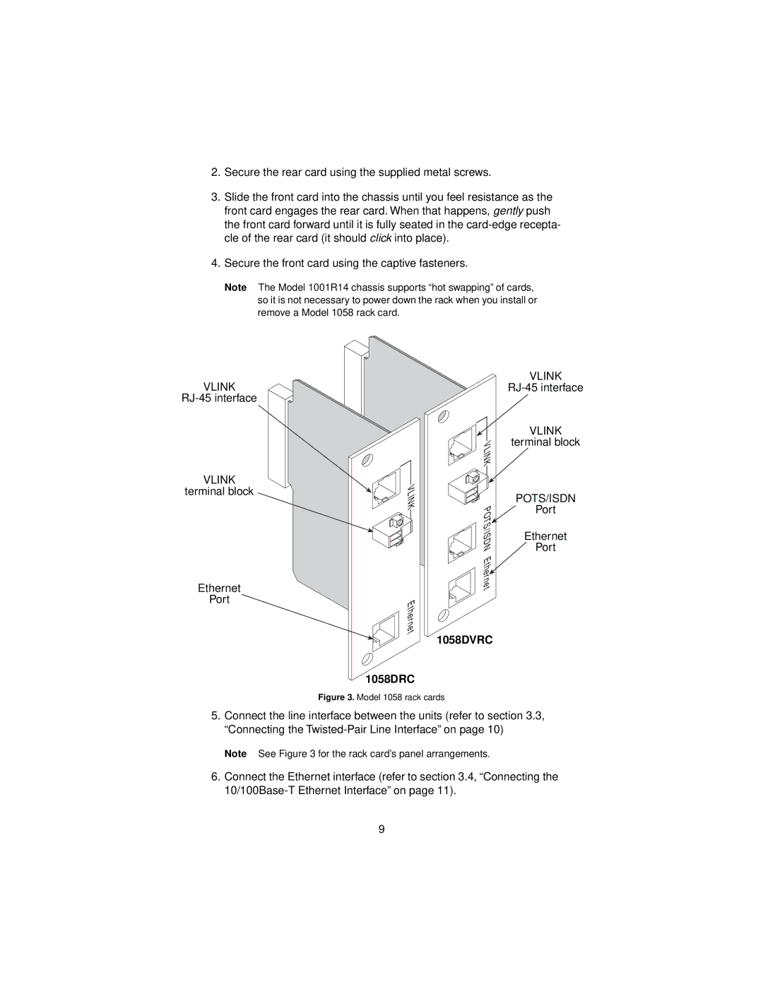
Figure 3. Model 1058 rack cards
5.Connect the line interface between the units (refer to section 3.3, “Connecting the
Note See Figure 3 for the rack card’s panel arrangements.
6.Connect the Ethernet interface (refer to section 3.4, “Connecting the
9
