2.0 GENERAL INFORMATION
Thank you for your purchase of this Patton Electronics product. This product has been thoroughly inspected and tested and is warranted for One Year parts and labor. If any questions or problems arise during installation or use of this product, please do not hesitate to contact Patton Electronics Technical Support at (301)
2.1FEATURES
•Data rates from 1.2 to 19.2 Kbps, switch selectable
•
•Distances up to 10 miles
•Tristate LED indicators
•
•Loopback test modes
•Internal or external clocking
•Hardware and software flow control support
•Externally powered
2.2DESCRIPTION
The Model 1070 Series synchronous short range modem is equipped with a virtual wish list of “bells and whistles”:
In addition, the Model 1070 is perfect for low power
The Model 1070 is housed in a sturdy metal case, and comes with either 115 or 220V external transformers. This is the
3.0 CONFIGURATION
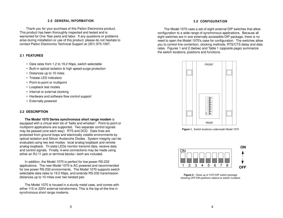
The Model 1070 uses a set of eight external DIP switches that allow configuration to a wide range of synchronous applications. Because all eight switches are in one externally accessible DIP package, there is no need to open the Model 1070's case for configuration. The switches allow you to control line contention, clocking methods, RTS/CTS delay and data rates. Figures 1 and 2 (below) and Table 1 (opposite page) summarize the switch locations, positions and functions.
FRONT
|
|
|
|
|
|
|
|
|
|
|
|
|
|
|
|
|
|
|
|
|
|
|
|
|
|
|
|
|
|
|
|
|
|
|
|
|
|
|
|
|
|
|
|
|
|
|
|
|
|
| 8 |
|
|
|
|
|
|
|
|
|
| 7 |
|
|
|
|
|
|
|
|
|
|
|
|
| |
|
|
|
|
|
|
| 6 |
|
|
|
|
|
|
|
|
|
| 5 |
|
|
|
|
|
|
|
|
|
| 4 |
|
|
|
|
|
|
|
|
|
| 3 |
|
|
|
|
|
|
| ON |
|
| 2 |
|
|
|
|
|
|
|
|
| 1 |
|
|
| |
|
|
|
|
|
|
|
|
|
|
|
|
|
|
|
|
|
|
|
|
|
|
|
|
|
|
|
|
|
|
|
|
|
REAR
Figure 1. Switch locations underneath Model 1070
ON
ON |
|
|
|
|
|
|
|
|
|
|
|
|
|
|
|
| ||
|
|
|
|
|
|
|
|
|
|
|
|
|
|
|
|
|
|
|
|
|
|
|
|
|
|
|
|
|
|
|
|
|
|
|
|
|
|
|
|
|
|
|
|
|
|
|
|
|
|
|
|
|
|
|
|
|
|
|
|
|
|
|
|
|
|
|
|
|
|
|
|
|
|
|
|
|
|
|
|
|
|
|
|
|
|
|
|
|
|
|
|
|
|
|
1 |
| 2 | 3 | 4 | 5 | 6 | 7 | 8 |
| OFF | ||||||||
|
|
|
|
|
|
|
|
|
|
|
|
|
|
|
|
| ||
Figure 2. Close up of 1070 DIP switch package
showing OFF/ON positions relative to switch numbers
3 | 4 |
