SWITCH SUMMARY TABLE
Position | Function | Factory Default | ||
|
|
|
|
|
Switch 1 | Data Rate | Off | } |
|
Switch 2 | Data Rate | Off | 9,600 Bps | |
Switch 3 | Data Rate | On |
| |
|
|
|
|
|
Switch 4 | Not Used | N/A |
|
|
|
|
|
|
|
Switch 5 | Transmit Clock | Off |
| Internal Clock |
|
|
|
|
|
Switch 6 | RTS/CTS Delay | On | } 8 ms | |
Switch 7 | RTS/CTS Delay | Off | ||
|
|
|
|
|
Switch 8 | Carrier Control | Off |
| Constant |
|
|
|
|
|
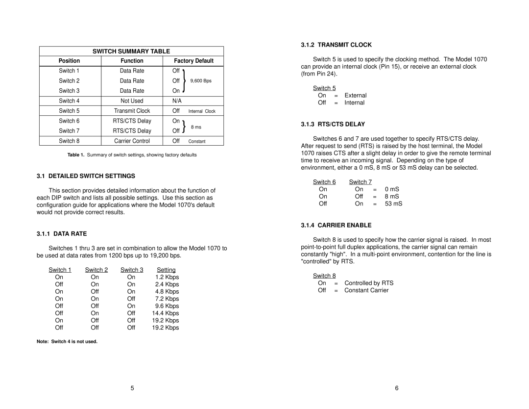
Table 1. Summary of switch settings, showing factory defaults
3.1 DETAILED SWITCH SETTINGS
This section provides detailed information about the function of each DIP switch and lists all possible settings. Use this section as configuration guide for applications where the Model 1070's default would not provide correct results.
3.1.1 DATA RATE
Switches 1 thru 3 are set in combination to allow the Model 1070 to be used at data rates from 1200 bps up to 19,200 bps.
Switch 1 | Switch 2 | Switch 3 | Setting | |
On | On | On | 1.2 Kbps | |
Off | On | On | 2.4 | Kbps |
On | Off | On | 4.8 | Kbps |
On | On | Off | 7.2 | Kbps |
Off | Off | On | 9.6 | Kbps |
Off | On | Off | 14.4 | Kbps |
On | Off | Off | 19.2 | Kbps |
Off | Off | Off | 19.2 | Kbps |
Note: Switch 4 is not used.
3.1.2 TRANSMIT CLOCK
Switch 5 is used to specify the clocking method. The Model 1070 can provide an internal clock (Pin 15), or receive an external clock (from Pin 24).
Switch 5
On = External
Off = Internal
3.1.3 RTS/CTS DELAY
Switches 6 and 7 are used together to specify RTS/CTS delay. After request to send (RTS) is raised by the host terminal, the Model 1070 raises CTS after a slight delay in order to give the remote terminal time to receive an incoming signal. Depending on the type of environment, either a 0 mS, 8 mS or 53 mS delay can be selected.
Switch 6 | Switch 7 |
|
|
On | On | = | 0 mS |
On | Off | = | 8 mS |
Off | On | = | 53 mS |
3.1.4 CARRIER ENABLE
Switch 8 is used to specify how the carrier signal is raised. In most
Switch 8 |
| |
On | = | Controlled by RTS |
Off | = | Constant Carrier |
5 | 6 |
