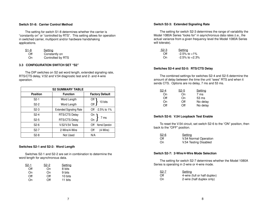
1080A, 1080A-64 specifications
The Patton Electronics 1080A-64 and 1080A are versatile communication devices designed to streamline data transmission and enhance connectivity in various environments. As part of Patton's extensive range of telecommunications solutions, these models reflect the latest technological advancements in serial-to-IP conversion, ensuring reliable and efficient communication across diverse networks.One of the standout features of the Patton 1080A-64 is its ability to support multiple serial ports, allowing seamless integration with a wide range of serial devices. This multi-port capability is particularly beneficial for businesses that operate various legacy systems, enabling them to bridge the gap between traditional serial protocols and modern IP-based networks. The 1080A is similarly equipped, ensuring that users can connect their existing infrastructure without extensive modifications.
Both models utilize advanced data encapsulation techniques, including the capability to handle standard protocols such as TCP, UDP, and RTP. This versatility ensures that users can implement the devices in various applications, including point-to-point and point-to-multipoint setups. Additionally, the incorporation of efficient data compression algorithms helps to optimize bandwidth usage, making these devices ideal for environments with limited data capacity.
Another significant characteristic of the Patton 1080A-64 and 1080A is their impressive security features. The devices are equipped with robust encryption options to protect data during transmission, ensuring that sensitive information remains secure against potential threats. This focus on security is particularly important for industries that handle confidential data, such as finance, healthcare, and government sectors.
The user-friendly interface of both models further enhances their appeal. With intuitive web-based management tools, administrators can easily configure settings, monitor performance, and troubleshoot issues in real time. This ease of use reduces downtime and allows businesses to maintain operational efficiency.
In terms of physical design, the Patton 1080A-64 and 1080A are built for durability and reliability. Their compact form factor and industrial-grade components make them suitable for deployment in various environments, from office settings to harsh industrial conditions.
Overall, the Patton Electronics 1080A-64 and 1080A stand out as reliable solutions for modern communication needs, combining multi-port support, advanced encapsulation technologies, strong security features, and user-friendly management capabilities. These models enable organizations to modernize their data transmission processes while maintaining compatibility with existing serial devices, making them valuable assets in today’s interconnected world.

