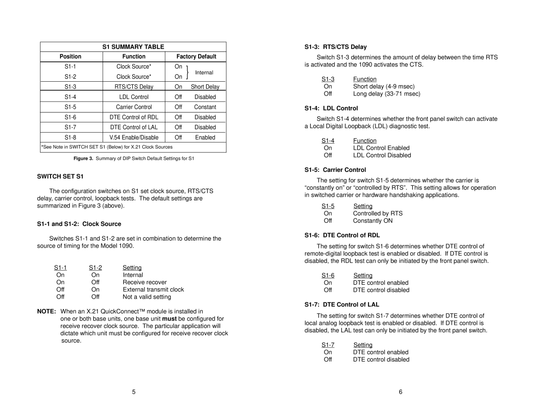
S1 SUMMARY TABLE
| Position | Function | Factory Default |
| ||
|
|
|
|
|
|
|
| Clock Source* | On | } | Internal |
| |
| Clock Source* | On |
| |||
|
|
|
|
|
|
|
| RTS/CTS Delay | On |
| Short Delay |
| |
| LDL Control | Off |
| Disabled |
| |
|
|
|
|
|
|
|
| Carrier Control | Off |
| Constant |
| |
|
|
|
|
|
|
|
| DTE Control of RDL | Off |
| Disabled |
| |
|
|
|
|
|
|
|
| DTE Control of LAL | Off |
| Disabled |
| |
|
|
|
|
|
|
|
| V.54 Enable/Disable | Off |
| Enabled |
| |
|
|
|
|
|
|
|
*See Note in SWITCH SET S1 (Below) for X.21 Clock Sources
Figure 3. Summary of DIP Switch Default Settings for S1
SWITCH SET S1
The configuration switches on S1 set clock source, RTS/CTS delay, carrier control, loopback tests. The default settings are summarized in Figure 3 (above).
S1-1 and S1-2: Clock Source
Switches
Setting | ||
On | On | Internal |
On | Off | Receive recover |
Off | On | External transmit clock |
Off | Off | Not a valid setting |
NOTE: When an X.21 QuickConnect™ module is installed in
one or both base units, one base unit must be configured for receive recover clock source. The particular application will dictate which unit must be configured for receive recover clock source.
S1-3: RTS/CTS Delay
Switch
Function | |
On | Short delay |
Off | Long delay |
S1-4: LDL Control
Switch
Function | |
On | LDL Control Enabled |
Off | LDL Control Disabled |
S1-5: Carrier Control
The setting for switch
Setting | |
On | Controlled by RTS |
Off | Constantly ON |
S1-6: DTE Control of RDL
The setting for switch
Setting | |
On | DTE control enabled |
Off | DTE control disabled |
S1-7: DTE Control of LAL
The setting for switch
Setting | |
On | DTE control enabled |
Off | DTE control disabled |
5 | 6 |