2.0 GENERAL INFORMATION
Thank you for your purchase of this Patton Electronics product. This product has been thoroughly inspected and tested and is warrant- ed for One Year parts and labor. If any questions or problems arise during installation or use of this product, please do not hesitate to con- tact Patton Electronics Technical Support at (301)
2.1 FEATURES
•Synchronous data rates of 256 and 512 kbps
•Frequency Shift Key (FSK) modulation
•Full or half duplex operation over two twisted pair
•
•V.54 compliant local and remote loopback tests (DTE or front panel activated)
•V.52 compliant Bit Error Rate (BER) test pattern generator
•Replaceable
•Internal, external or receive recovered clocking options
•Automatic equalization
•Made in the U.S.A.
2.2 DESCRIPTION
The Patton Model 1093 Synchronous Short Range Modem is designed for
The Model 1093 features replaceable
3.0 CONFIGURATION
The Model 1093 is equipped with one set of eight DIP switches, and one set of four DIP switches (all externally accessible). These DIP switches allow configuration of clock source, carrier control, loopback tests and data rate. This section describes switch locations and explains all possible configurations.
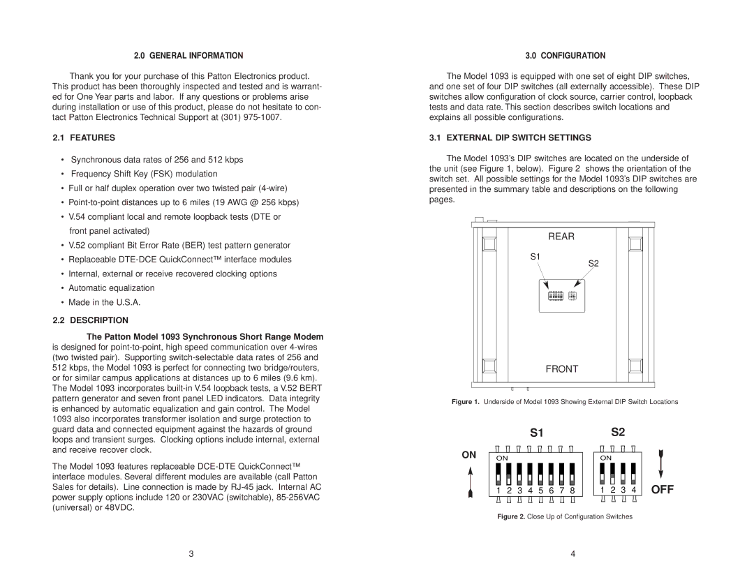
3.1 EXTERNAL DIP SWITCH SETTINGS
The Model 1093’s DIP switches are located on the underside of the unit (see Figure 1, below). Figure 2 shows the orientation of the switch set. All possible settings for the Model 1093’s DIP switches are presented in the summary table and descriptions on the following pages.
REAR
S1
S2
8 | 7 | 6 | 5 | 4 | 3 | 2 | 1 |
| 4 | 3 | 2 | 1 |
|
|
|
|
|
|
|
|
|
|
|
|
|
|
|
|
|
|
|
| ON |
|
|
| ON | |
FRONT
Figure 1. Underside of Model 1093 Showing External DIP Switch Locations
|
|
|
| S1 |
|
|
|
| S2 |
|
| ||
ON | ON |
|
|
|
|
|
| ON |
|
|
| ||
| 1 | 2 | 3 | 4 | 5 | 6 | 7 | 8 | 1 | 2 | 3 | 4 | OFF |
| Figure 2. Close Up of Configuration Switches |
| |||||||||||
3 | 4 |