3.1.2 CONFIGURATION SWITCH SET “S2”
The DIP switches on S2 set word length, extended signaling rate, RTS/CTS delay and V.52 and V.54 diagnostic test. The default settings are summarized in the table below. Following the table is a description of all possible
S2 SUMMARY TABLE
Position | Function | Factory Default |
| ||
|
|
|
|
|
|
Word Length | Off | } 10 bits | |||
Word Length | Off | ||||
|
|
|
|
| |
Extended Signaling Rate | Off | ||||
|
|
|
|
|
|
RTS/CTS Delay | On | } 7 mS | |||
RTS/CTS Delay | On | ||||
|
|
|
|
|
|
Future Use | - |
|
|
| |
|
|
|
|
|
|
Future Use | - |
|
|
| |
|
|
|
|
|
|
V.52/V.54 Tests | Off | Enable | |||
|
|
|
|
|
|
S2-1 and S2-2: Word Length
Switches
Setting | ||
Off | On | 8 bits |
On | On | 9 bits |
Off | Off | 10 bits |
On | Off | 11 bits |
S2-3: Extended Signaling Rate
The setting for switch
Setting |
| ||
Off |
| Basic | |
On | Extended | ||
S2-4 and S2-5: RTS/CTS Delay
The combined settings for switches
Setting | ||
On | On | 7 mS |
Off | On | 53 mS |
On | Off | No delay |
Off | Off | No delay |
S2-8: V.54 Loopback Test Enable
To reset the V.54 circuit, set switch
Setting | ||
Off | V.54 | Enable |
On | V.54 | Disable |
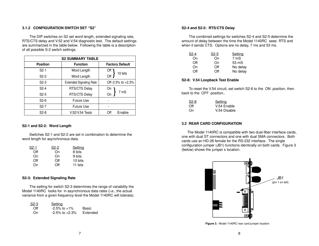
3.2 REAR CARD CONFIGURATION
The Model 1140RC is compatible with two
JB1
(pin 1 on left)
Figure 3. Model 1140RC rear card jumper location
7 | 8 |