Switching the Power Supply On and Off
The power supply on/off switch is located on the front panel. When plugged in and switched on, a red front panel LED will glow. Since the Model 1000R16 is a “hot swappable” rack,it is not necessary for any cards to be installed before switching on the power supply. The power supply may be switched off at any time without harming the installed cards.
NOTE: Please refer to the Model 1000RP Series User Manual AC and DC Rack Mount Power Supplies for fuse and power card replacement information.
4.2 INSTALLING THE MODEL 1140RC INTO THE CHASSIS
The Model 1140RC is comprised of a front card and a rear card. The two cards meet inside the rack chassis and plug into each other via mating 50 pin card edge connectors. Use the following steps as a guideline for installing each Model 1140RC into the Model 1000R16 rack chassis:
1.Slide the rear card into the back of the chassis along the metal rails.
2.Secure the rear card using the metal screws provided.
3.Slide the front card into the front of the chassis. It should meet the rear card when it’s almost all the way into the chassis.
4.Push the front card gently into the
5.Secure the front card using the thumb screws.
NOTE: Since the Model 1000R16 chassis allows “hot swapping” of cards, it is not necessary to power down the rack when you install or remove a Model 1140RC.
4.3 WIRING UP THE MODEL 1140RC
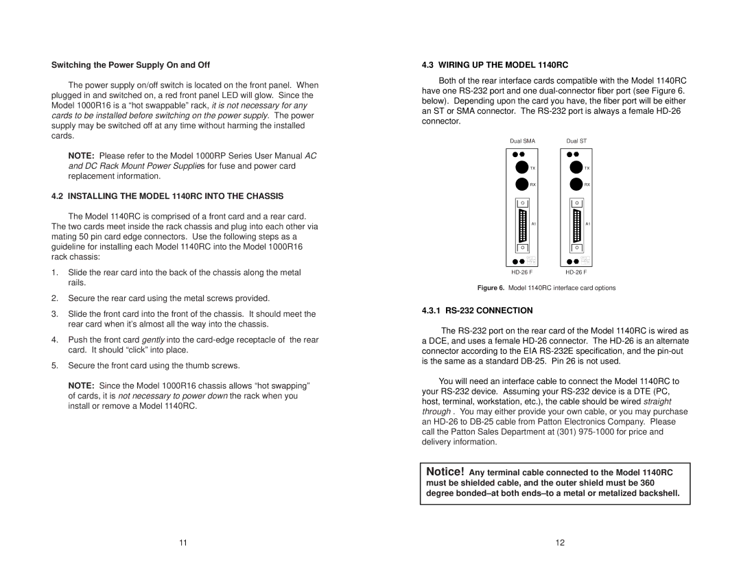
Both of the rear interface cards compatible with the Model 1140RC have one
Dual SMA |
| Dual ST | ||||||||||||
|
|
|
|
|
|
|
|
|
|
|
|
|
|
|
|
|
|
| TX |
|
|
|
|
| TX | ||||
|
|
|
| RX |
|
|
|
|
| RX | ||||
|
|
|
| A1 |
|
|
|
|
| A1 | ||||
|
|
|
|
|
|
|
|
| ||||||
|
|
|
|
|
|
|
|
| ||||||
|
|
|
|
|
|
|
|
|
|
|
|
|
|
|
|
|
|
|
|
|
|
|
|
|
|
|
|
|
|
|
|
|
|
|
|
|
|
|
|
|
|
|
|
|
|
|
|
|
|
|
|
|
|
|
|
|
|
|
|
|
|
|
|
|
|
|
|
|
|
|
|
|
|
|
|
|
|
|
|
|
|
|
|
|
|
|
|
|
|
|
|
|
|
|
|
|
|
|
|
|
|
|
|
|
|
|
|
|
|
|
|
|
|
|
|
|
|
|
|
Figure 6. Model 1140RC interface card options
4.3.1 RS-232 CONNECTION
The
You will need an interface cable to connect the Model 1140RC to your
Notice! Any terminal cable connected to the Model 1140RC must be shielded cable, and the outer shield must be 360 degree
11 | 12 |