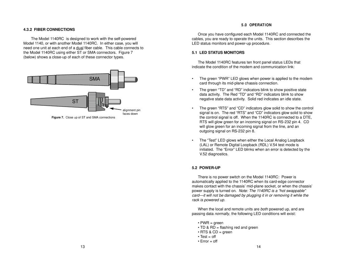
4.3.2 FIBER CONNECTIONS
The Model 1140RC is designed to work with the
SMA
ST
![]() alignment pin faces down
alignment pin faces down
Figure 7. Close up of ST and SMA connections
13
5.0 OPERATION
Once you have configured each Model 1140RC and connected the cables, you are ready to operate the units. This section describes the LED status monitors and
5.1 LED STATUS MONITORS
The Model 1140RC features ten front panel status LEDs that indicate the condition of the modem and communication link:
•The green “PWR” LED glows when power is applied to the modem card through its
•The green “TD” and “RD” indicators blink to show positive state data activity. The Red “TD” and “RD” indicators blink to show negative state data activity. Solid red indicates an idle state.
•The green “RTS” and “CD” indicators glow solid to show the control signal is on. The red “RTS” and “CD” indicators glow solid to show the control signal is off. When the 1140RC is connected to a DTE, RTS will glow green for an incoming signal on
•The “Test” LED glows when either the Local Analog Loopback (LAL) or Remote Digital Loopback (RDL) V.54 test mode is initiated. The “Error” LED blinks when an error is detected by the V.52 diagnostics.
5.2 POWER-UP
There is no power switch on the Model 1140RC: Power is automatically applied to the 1140RC when its
When the local and remote units are both powered up, and are passing data normally, the following LED conditions will exist:
•PWR = green
•TD & RD = flashing red and green
•RTS & CD = green
•Test = off
•Error = off
14