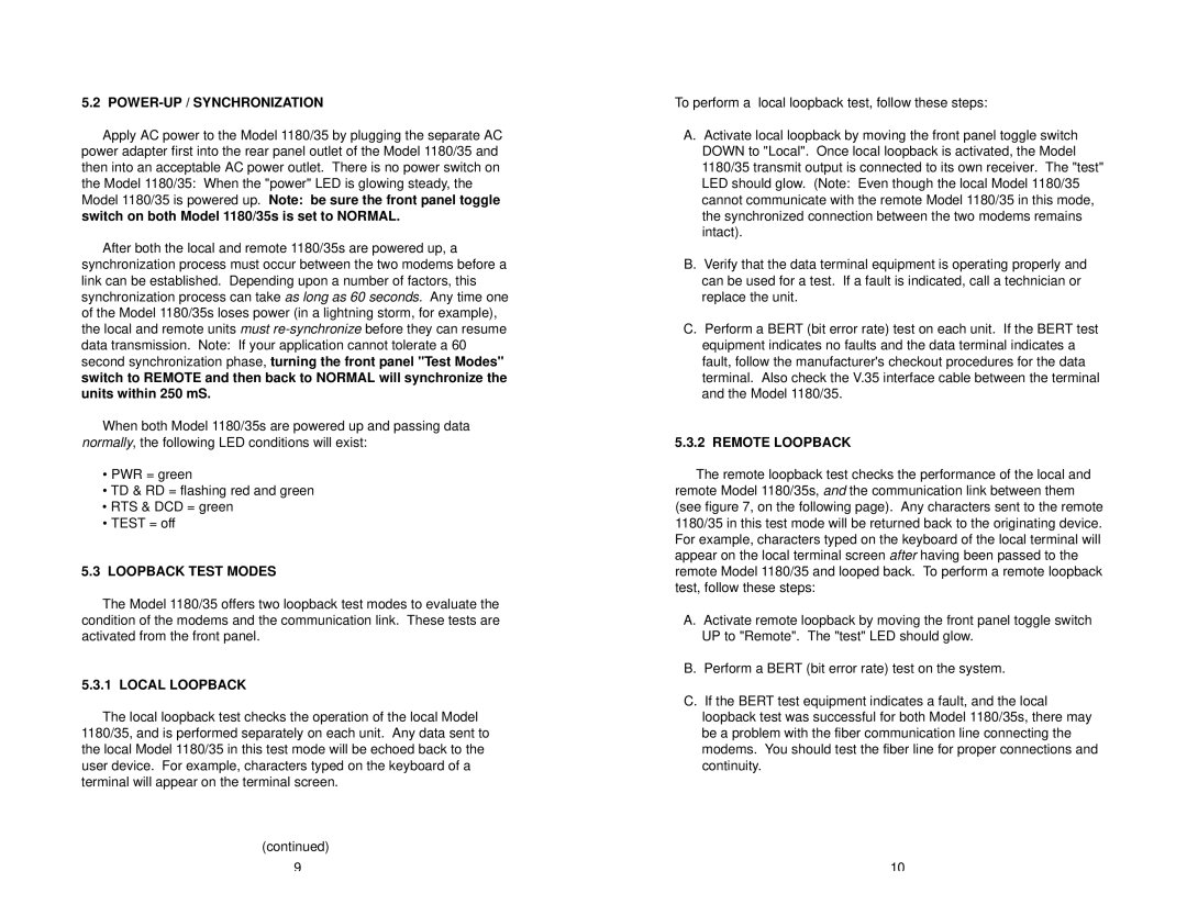
1180/35 specifications
The Patton Electronic 1180/35 is a versatile and robust device designed for a variety of telecommunication applications. Known for its reliability, the 1180/35 is particularly adept in environments that demand low power consumption and high performance. One of its standout features is its ability to support multiple communication protocols, making it an excellent choice for businesses looking to streamline their operations and minimize the need for additional hardware.A key technology employed in the 1180/35 is its advanced digital signal processing (DSP). This technology enhances call quality and optimizes voice clarity, which is crucial for any organization relying on telephony for customer relations. With DSP, the device can effectively eliminate background noise and minimize latency, ensuring a seamless communication experience.
The 1180/35 also supports various interfaces, including Ethernet and serial connections, providing flexibility for integration into existing networks. This broad compatibility allows users to easily integrate the device with their current setup, making it a cost-effective solution for upgrading communication systems without overhauling entire infrastructures.
In addition to its connectivity features, the Patton 1180/35 is equipped with built-in security protocols. This includes encryption capabilities that protect sensitive voice and data traffic from potential eavesdropping or interception. As cybersecurity becomes ever more critical in communication technology, the inclusion of these security features makes the 1180/35 an attractive option for businesses concerned about data integrity.
Another notable characteristic of the 1180/35 is its compact design, which enables easy placement in office environments. Despite its small footprint, the device is rugged and designed to withstand the demands of everyday use, ensuring longevity and durability.
Power efficiency is another remarkable feature. The 1180/35 operates with low power consumption, allowing for reduced operational costs while also being environmentally friendly. This aspect is increasingly appealing to businesses looking to reduce their carbon footprint while maintaining high performance in their communication tools.
In summary, the Patton Electronic 1180/35 stands out in the telecommunications landscape due to its advanced features, including digital signal processing, versatile connectivity options, built-in security, compact design, and power efficiency. These characteristics make it an ideal choice for modern businesses seeking reliable and effective communication solutions. It is a product that combines quality with practicality, poised to meet the needs of various communication scenarios.
