4.2 LED STATUS MONITORS
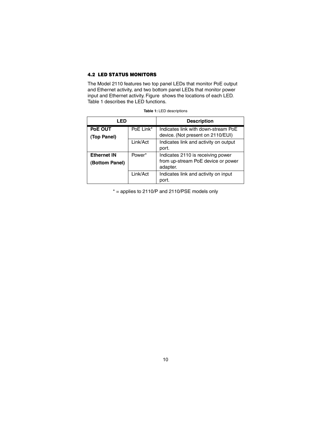
The Model 2110 features two top panel LEDs that monitor PoE output and Ethernet activity, and two bottom panel LEDs that monitor power input and Ethernet activity. Figure shows the locations of each LED. Table 1 describes the LED functions.
Table 1: LED descriptions
LED |
| Description |
|
|
|
PoE OUT | PoE Link* | Indicates link with |
(Top Panel) |
| device. (Not present on 2110/EUI) |
|
| |
| Link/Act | Indicates link and activity on output |
|
| port. |
|
|
|
Ethernet IN | Power* | Indicates 2110 is receiving power |
(Bottom Panel) |
| from |
| adapter. | |
|
| |
|
|
|
| Link/Act | Indicates link and activity on input |
|
| port. |
|
|
|
* = applies to 2110/P and 2110/PSE models only
10
