Model 2110
(Front and Top)
IN | PoE |
|
2110 Model Types:
2110/P - PoE/Ethernet 2110/PSE - PoE/Ethernet 2110/EUI - Ethernet only
PoE and/or Ethernet
Output
RJ-45 port
|
|
|
|
|
|
| t |
|
|
|
|
|
|
|
|
|
|
| |
|
| A |
| E |
| e | rn | r | to |
|
|
|
|
| |||||
|
|
| S | U |
| S |
|
|
|
|
|
|
| ||||||
|
|
|
| d, |
|
| /P |
| e | th |
|
| c | je |
|
| |||
|
|
|
|
|
|
|
| 0 |
|
|
|
|
|
|
| ||||
|
|
|
|
|
| arylan | 1 |
| E | & |
| In |
| ||||||
|
|
|
|
|
|
|
| 2 |
|
|
| ||||||||
|
|
|
|
|
|
|
|
|
| 1 |
|
|
|
|
|
|
| ||
|
|
|
|
|
|
|
|
| M |
|
| l |
|
|
| E |
| ||
T |
|
|
|
|
|
|
|
|
| urg, |
| e |
|
| o | P | |||
U |
|
|
|
|
|
|
|
|
|
| do | M | |||||||
| O | E |
|
|
|
|
|
|
| rsbe | aith |
| |||||||
|
|
|
|
|
|
|
|
|
|
|
| G |
| ||||||
|
|
|
|
|
|
|
|
|
|
|
|
|
|
|
|
| |||
|
|
|
| o |
|
|
|
|
|
|
|
|
|
|
|
|
|
| |
|
|
|
|
| P |
|
|
|
|
|
|
|
|
|
|
|
| ||
| S | CO | MP |
|
|
| |
B |
|
|
|
| |||
EE | IN |
| LI |
|
|
| |
| EF |
| O ES |
|
|
| |
____ | OR | ST | FT WI |
|
|
| |
| E COALLAHE FTH P |
|
| ||||
_____ |
|
| NNECTIONCC RART | 1 |
| ||
__ | __ |
|
| TI IN UL | 5 | CL | |
__ |
| NG | ST | ES | |||
Patton__E____ |
| ______ | TO SRUUCT.I ASS A | ||||
lectro __ |
|
|
| ___ |
| PP | ON |
nics___ |
|
|
| __ |
| LY.S | |
__ |
|
|
| __ |
|
| |
__ |
|
|
|
| __ |
|
|
__ |
|
|
| _ |
|
| |
M | __ |
|
|
|
|
|
|
| ade __ |
|
|
|
|
|
|
| in __ |
|
|
|
|
| |
| the __ |
|
|
|
| ||
|
| USA__ |
|
|
| ||
PoE and/or Ethernet | Model 2110 | |
Input | ||
(Back and Bottom) | ||
| ||
Power jack |
| |
(EUI models only) |
|
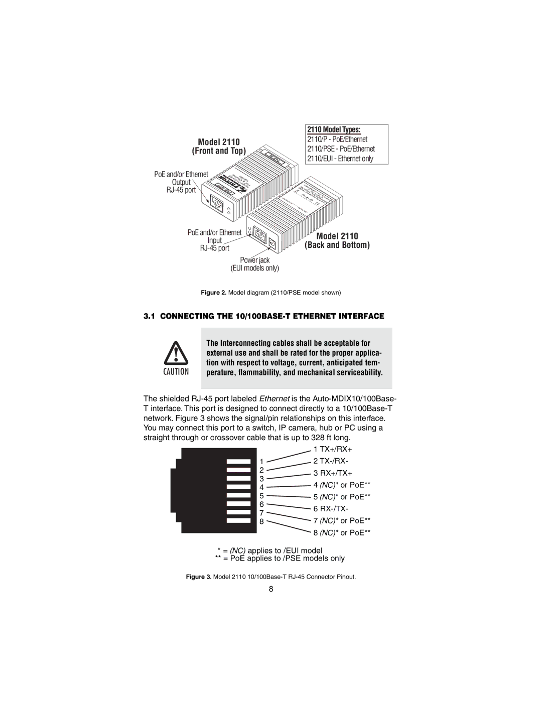
Figure 2. Model diagram (2110/PSE model shown)
3.1 CONNECTING THE
The Interconnecting cables shall be acceptable for
external use and shall be rated for the proper applica-
tion with respect to voltage, current, anticipated tem-
CAUTION perature, flammability, and mechanical serviceability.
The shielded
| 1 TX+/RX+ | ||
1 | 2 | ||
2 | 3 RX+/TX+ | ||
3 | |||
4 | (NC)* or PoE** | ||
4 | |||
|
| ||
5 | 5 | (NC)* or PoE** | |
6 | 6 | ||
7 | |||
7 | (NC)* or PoE** | ||
8 | |||
| 8 | (NC)* or PoE** | |
* = (NC) applies to /EUI model
** = PoE applies to /PSE models only
Figure 3. Model 2110 10/100Base-T RJ-45 Connector Pinout.
8
