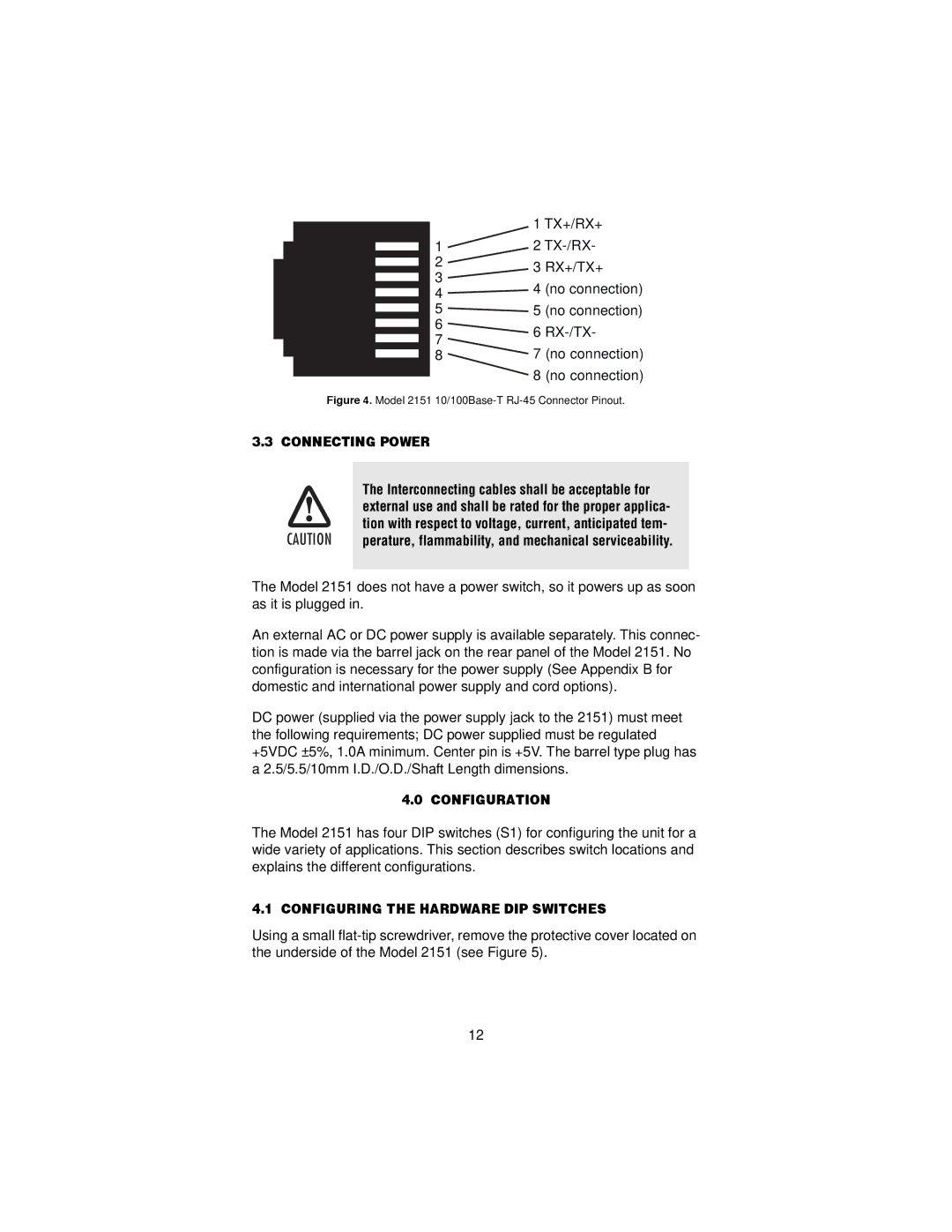
| 1 TX+/RX+ |
1 | 2 |
23 RX+/TX+
4 | 4 | (no connection) | |
|
| ||
5 | 5 | (no connection) | |
6 | 6 | ||
7 | |||
7 (no connection) | |||
8 | |||
8 (no connection)
Figure 4. Model 2151 10/100Base-T RJ-45 Connector Pinout.
3.3 CONNECTING POWER
The Interconnecting cables shall be acceptable for
external use and shall be rated for the proper applica-
tion with respect to voltage, current, anticipated tem-
CAUTION perature, flammability, and mechanical serviceability.
The Model 2151 does not have a power switch, so it powers up as soon as it is plugged in.
An external AC or DC power supply is available separately. This connec- tion is made via the barrel jack on the rear panel of the Model 2151. No configuration is necessary for the power supply (See Appendix B for domestic and international power supply and cord options).
DC power (supplied via the power supply jack to the 2151) must meet the following requirements; DC power supplied must be regulated +5VDC ±5%, 1.0A minimum. Center pin is +5V. The barrel type plug has a 2.5/5.5/10mm I.D./O.D./Shaft Length dimensions.
4.0 CONFIGURATION
The Model 2151 has four DIP switches (S1) for configuring the unit for a wide variety of applications. This section describes switch locations and explains the different configurations.
4.1 CONFIGURING THE HARDWARE DIP SWITCHES
Using a small
12