4.0 CONFIGURATION (MODEL 2168 ONLY)
The CopperLink Ethernet Extender has eight DIP switches for configur- ing the unit for a wide variety of applications. This section describes switch locations and explains the different configurations.
4.1 CONFIGURING THE HARDWARE DIP SWITCHES
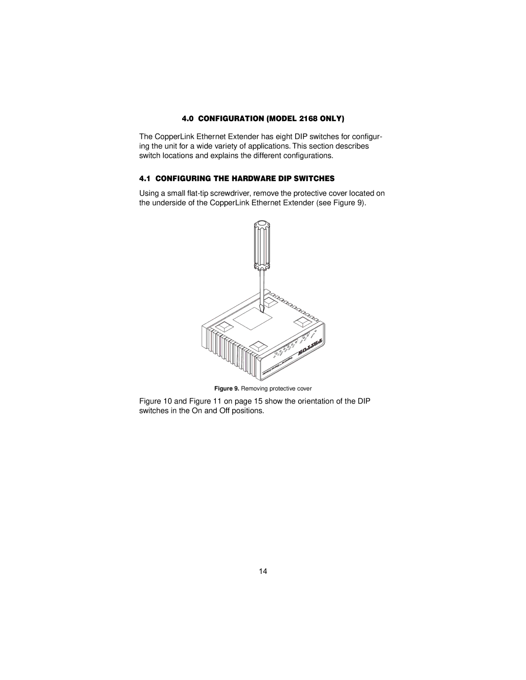
Using a small
Figure 9. Removing protective cover
Figure 10 and Figure 11 on page 15 show the orientation of the DIP switches in the On and Off positions.
14