| Link | Power |
Ethernet |
| |
|
|
|
|
|
|
|
|
|
|
|
|
|
| hgi | H |
|
|
|
|
|
|
|
|
|
| ep | S |
| |
|
|
|
|
|
|
|
| tE | de |
|
|
| |
|
|
|
|
|
|
| eh |
|
|
|
| ||
|
|
|
|
|
| nr |
|
|
|
|
| ||
|
|
|
|
| te |
|
|
|
|
|
| ||
|
| et | xE | oC |
|
|
|
|
|
| |||
| dn | pp |
|
|
|
|
|
| |||||
re | INL | re |
|
|
|
|
|
|
|
| |||
|
|
|
|
|
|
|
|
|
| ||||
™K |
|
|
|
|
|
|
|
|
|
| |||
|
|
|
|
|
|
|
|
|
|
|
| ||
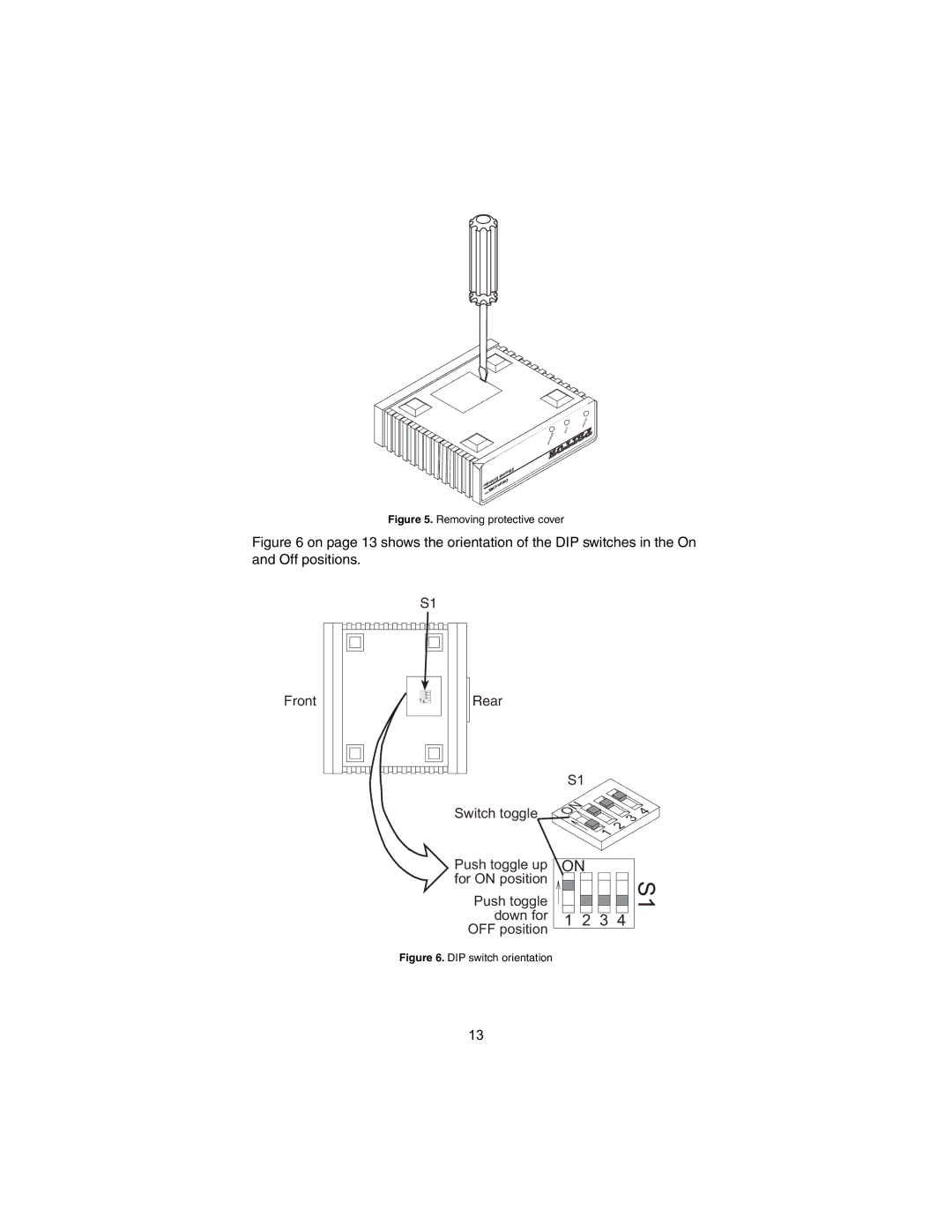
Figure 5. Removing protective cover
Figure 6 on page 13 shows the orientation of the DIP switches in the On and Off positions.
Front
S1 | |
ON | 213 4 |
| Rear |
| Switch toggle |
S1
ON |
|
| 3 | 4 |
|
| 2 |
| |
| 1 |
|
| |
|
|
|
|
Push toggle up | ON | |||||||
for ON position |
|
|
|
|
|
|
| S1 |
|
|
|
|
|
|
| ||
Push toggle |
|
|
|
|
|
|
| |
|
|
|
|
|
|
| ||
|
|
|
|
|
|
| ||
down for |
|
|
|
|
|
|
|
|
1 | 2 | 3 | 4 |
| ||||
OFF position |
|
|
|
|
|
|
|
|
Figure 6. DIP switch orientation
13
