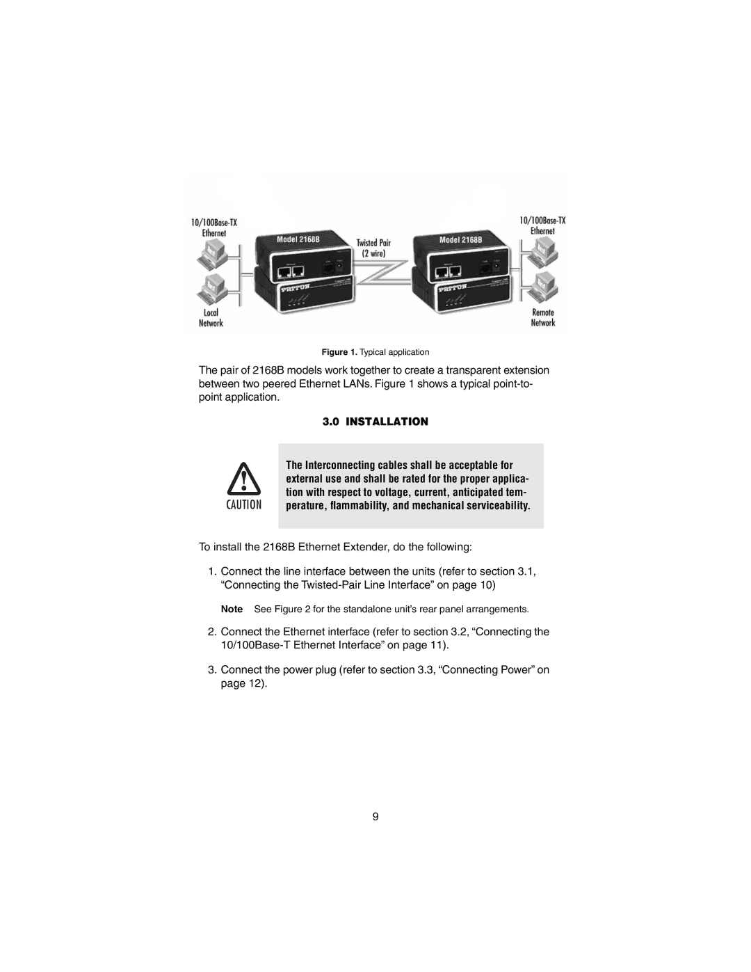
Figure 1. Typical application
The pair of 2168B models work together to create a transparent extension between two peered Ethernet LANs. Figure 1 shows a typical
3.0 INSTALLATION
The Interconnecting cables shall be acceptable for
external use and shall be rated for the proper applica-
tion with respect to voltage, current, anticipated tem-
CAUTION perature, flammability, and mechanical serviceability.
To install the 2168B Ethernet Extender, do the following:
1.Connect the line interface between the units (refer to section 3.1, “Connecting the
Note See Figure 2 for the standalone unit’s rear panel arrangements.
2.Connect the Ethernet interface (refer to section 3.2, “Connecting the
3.Connect the power plug (refer to section 3.3, “Connecting Power” on page 12).
9
