2.0 GENERAL INFORMATION
Thank you for your purchase of this Patton Electronics product. This product has been thoroughly inspected by Patton's qualified technicians. If any questions or problems arise during installation or use of this product, please do not hesitate to contact Patton Electronics Technical Support at (301)
2.1FEATURES
•Synchronous data rates of 56 or 64 Kbps
•Full duplex communication over two dedicated twisted pairs
•Supports distances to 3.4 miles over 26 AWG wire
•Selectable internal, external or network rcv/recover clock options
•
•Works with 56 Kbps DDS, 64 Kbps Clear Channel, or private twisted pair circuits
•Switchable Circuit Assurance feature
•Externally accessible configuration switches
•Six front panel LEDs monitor communication and test status
•
•
•V.35 version has either
•
2.2DESCRIPTION
The Model 2450 DDS & Clear Channel CSU/DSU is a standalone , AC powered CSU/DSU designed for
For user convenience, the Model 2450’s DIP switches are externally accessible, so there is no need to open the case to configure the unit. The Model 2450’s
3.0 CONFIGURATION
The Model 2450 is easy to install and is ruggedly designed for excellent reliability: just set it and forget it. The following instructions will help you set up and install the Model 2450 properly.
3.1 CONFIGURATION SWITCHES
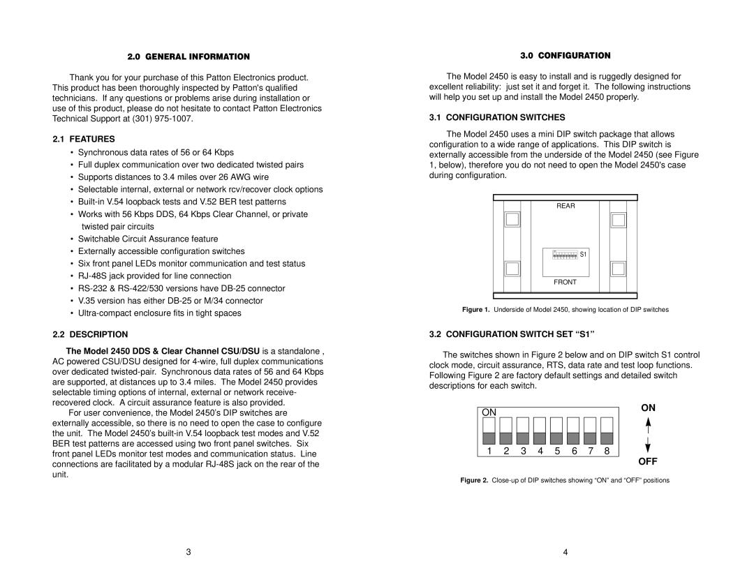
The Model 2450 uses a mini DIP switch package that allows configuration to a wide range of applications. This DIP switch is externally accessible from the underside of the Model 2450 (see Figure 1, below), therefore you do not need to open the Model 2450's case during configuration.
REAR
|
|
|
|
|
|
|
|
|
|
|
|
|
|
|
|
|
|
|
|
|
|
|
|
|
|
|
|
|
|
|
|
|
|
|
|
|
|
|
|
|
|
|
|
|
|
|
|
|
|
|
|
|
|
|
|
|
|
|
|
|
|
|
|
|
|
|
|
|
|
|
|
|
|
|
| ON |
|
|
|
|
|
|
| S1 |
|
|
|
|
|
|
|
|
| 1 | 2 | 3 | 4 | 5 | 6 | 7 | 8 |
|
|
|
|
| |
|
|
|
|
|
|
|
|
|
|
|
|
|
|
|
|
|
|
|
|
|
|
|
|
|
|
|
|
|
|
|
|
|
|
|
|
FRONT
Figure 1. Underside of Model 2450, showing location of DIP switches
3.2 CONFIGURATION SWITCH SET “S1”
The switches shown in Figure 2 below and on DIP switch S1 control clock mode, circuit assurance, RTS, data rate and test loop functions. Following Figure 2 are factory default settings and detailed switch descriptions for each switch.
|
|
|
|
|
|
|
|
|
|
|
|
|
|
|
|
| ON | |
ON |
|
|
|
|
|
|
|
|
|
|
|
|
|
| ||||
|
|
|
|
|
|
|
|
|
|
|
|
|
|
|
| |||
|
|
|
|
|
|
|
|
|
|
|
|
|
|
|
|
|
|
|
|
|
|
|
|
|
|
|
|
|
|
|
|
|
|
|
|
|
|
|
|
|
|
|
|
|
|
|
|
|
|
|
|
|
|
|
|
|
|
|
|
|
|
|
|
|
|
|
|
|
|
|
|
|
|
|
|
1 2 3 4 5 6 7 8
OFF
Figure 2. Close-up of DIP switches showing “ON” and “OFF” positions
3 | 4 |