4.2 DTE (TERMINAL) CONNECTION
The Model 2450 is wired to connect to a DTE. If your terminal device is DCE, call Patton Technical Support at (301)
Four versions of the Model 2450 are available, with respect to DTE interface and connector type (see Appendix C). All versions connect to the DTE using a straight through cable. When constructing or purchasing your interface cable, refer to the pinout diagrams in Appendix D.
4.3 AC POWER CONNECTION
Power is supplied to the Model 2450 by a 10 VAC, 1 A wall mount transformer. This transformer connects to the Model 2450 by means of a cannon jack on the rear panel. The Model 2450 is
4.3.1 120 VAC Power (US)
The 120 VAC adapter supplied with the standard version of the Model 2450 is a “wall mount” type, and may be plugged into any approved 120 VAC wall plug.
4.3.2 230 VAC Power (IEC)
The 230 VAC adapter supplied with the “international” version of the Model 2450 is equipped with an
5.0 OPERATION
Once you have configured the Model 2450 properly (see Section 3.0) and made line, DTE and power connections correctly (see Section 4.0), you are ready to operate the unit(s). (Note: the unit is operational as soon as power is
5.1 LED STATUS MONITORS
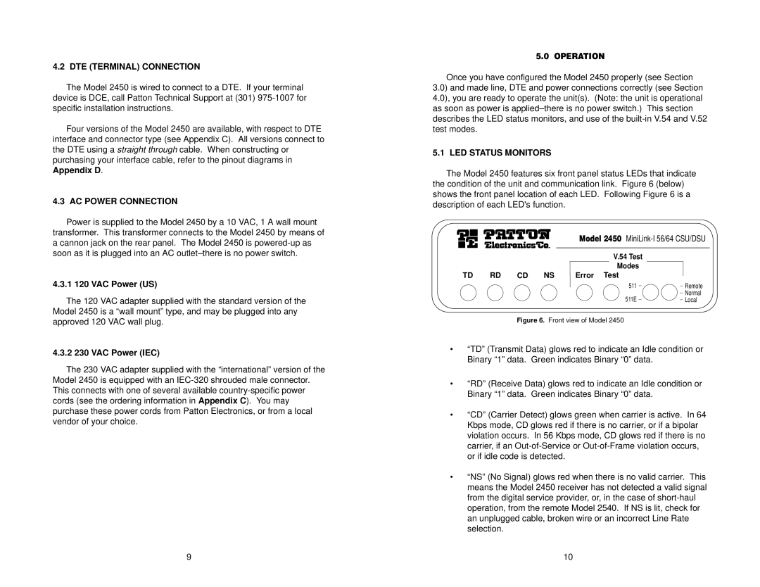
The Model 2450 features six front panel status LEDs that indicate the condition of the unit and communication link. Figure 6 (below) shows the front panel location of each LED. Following Figure 6 is a description of each LED's function.
Model 2450
V.54 Test
Modes
TD RD CD NS Error Test
511 | Remote |
511E | Normal |
Local |
Figure 6. Front view of Model 2450
•“TD” (Transmit Data) glows red to indicate an Idle condition or Binary “1” data. Green indicates Binary “0” data.
•“RD” (Receive Data) glows red to indicate an Idle condition or Binary “1” data. Green indicates Binary “0” data.
•“CD” (Carrier Detect) glows green when carrier is active. In 64 Kbps mode, CD glows red if there is no carrier, or if a bipolar violation occurs. In 56 Kbps mode, CD glows red if there is no carrier, if an
•“NS” (No Signal) glows red when there is no valid carrier. This means the Model 2450 receiver has not detected a valid signal from the digital service provider, or, in the case of
9 | 10 |