Switch S1-6: Front Panel Switch Enable/Disable
Switch
Activation | Description | |
Off | Enabled | Front panel switches may be used |
|
| to activate/terminate diagnostics |
On | Disabled | Front panel switches will have no |
|
| effect on operation of the unit |
Switch S1-7: DTE Loop Request Line Enable/Disable
The setting for switch
| DTE TM Line |
|
Activation | Description | |
Off | Enabled | DTE Loop request line switches |
|
| may be used to activate/terminate |
|
| diagnostics. |
On | Disabled | DTE loop request lines will |
|
| have no effect on operation of |
|
| the unit. |
Switch S1-8: Receive RDL Enable/Disable
Switch
Activation | Description | |
Off | Enabled | Unit wil respond to loop requests |
|
| from the remote device. |
On | Disabled | Unit wil ignore loop requests from |
|
| the remote device. |
4.0 INSTALLATION
The Model 2450 is designed for
4.1 LINE (NETWORK) CONNECTION
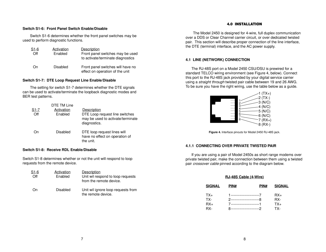
The
| 1 | (TX+) | |
1 | 2 | ||
3 | (N/C) | ||
2 | |||
3 | 4 | (N/C) | |
4 | 5 | (N/C) | |
5 | |||
6 | 6 | (N/C) | |
7 | |||
8 | 7 | (RX+) | |
| 8 |
Figure 4. Interface pinouts for Model 2450 RJ-48S jack.
4.1.1 CONNECTING OVER PRIVATE TWISTED PAIR
If you are using a pair of Model 2450s as short range modems over private twisted pair, make the connection between them using a twisted pair crossover cable pinned according to the diagram below.
|
| ||
SIGNAL | PIN# | PIN# | SIGNAL |
TX+ | 7 | RX+ | |
TX- | 8 | RX- | |
RX+ | 1 | TX+ | |
RX- | 2 | TX- | |
7 | 8 |
