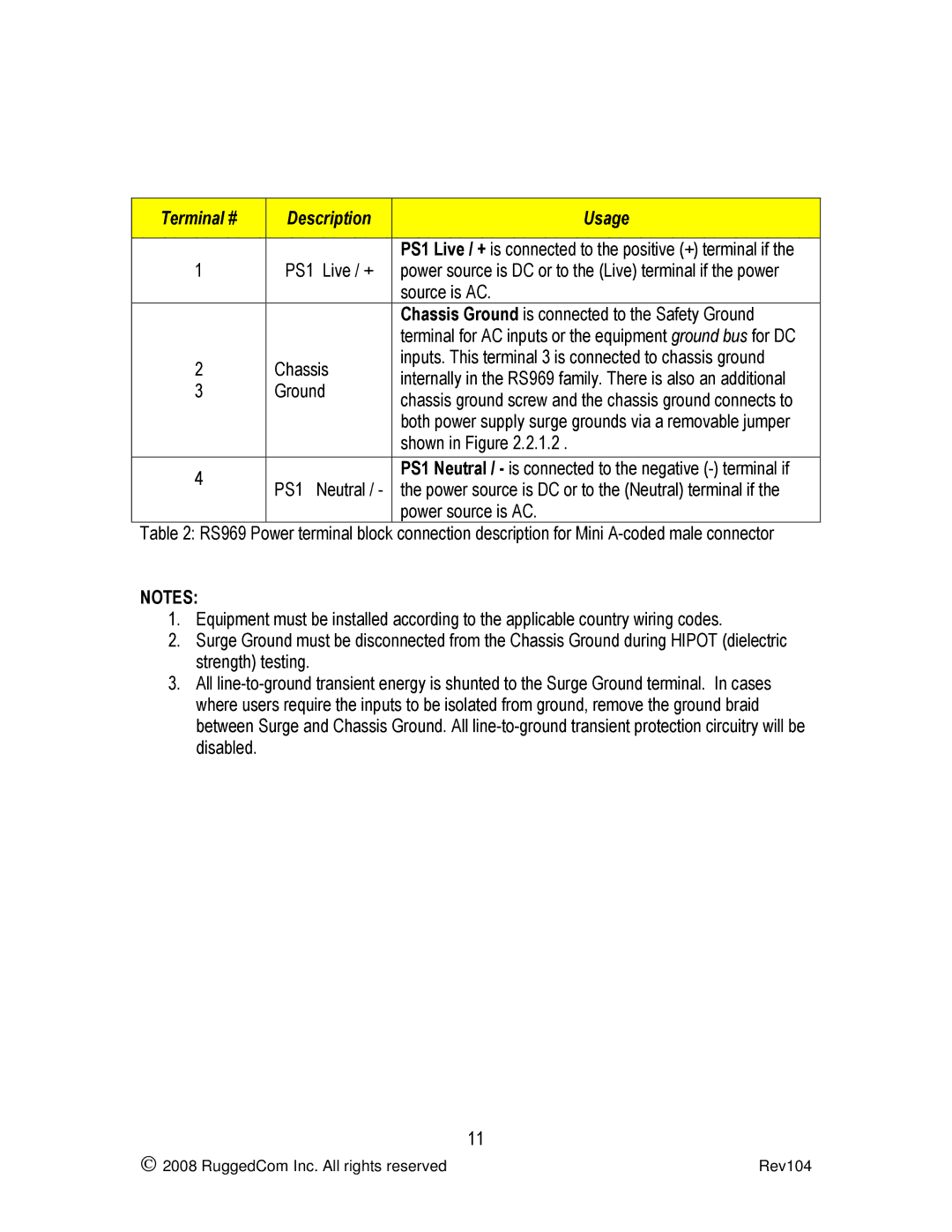
Terminal # |
|
| Description |
| Usage | |
|
|
|
|
|
|
|
|
|
|
|
|
| PS1 Live / + is connected to the positive (+) terminal if the |
1 |
|
| PS1 | Live / + |
| power source is DC or to the (Live) terminal if the power |
|
|
|
|
|
| source is AC. |
|
|
|
|
|
| Chassis Ground is connected to the Safety Ground |
|
|
|
|
|
| terminal for AC inputs or the equipment ground bus for DC |
2 |
|
| Chassis |
| inputs. This terminal 3 is connected to chassis ground | |
|
|
| internally in the RS969 family. There is also an additional | |||
3 |
|
| Ground |
| ||
|
|
| chassis ground screw and the chassis ground connects to | |||
|
|
|
|
|
| |
|
|
|
|
|
| both power supply surge grounds via a removable jumper |
|
|
|
|
|
| shown in Figure 2.2.1.2 . |
|
|
|
|
|
|
|
4 |
|
|
|
|
| PS1 Neutral / - is connected to the negative |
|
| PS1 | Neutral / - |
| the power source is DC or to the (Neutral) terminal if the | |
|
|
|
| |||
|
|
|
|
|
| power source is AC. |
Table 2: RS969 Power terminal block connection description for Mini
NOTES:
1.Equipment must be installed according to the applicable country wiring codes.
2.Surge Ground must be disconnected from the Chassis Ground during HIPOT (dielectric strength) testing.
3.All
| 11 |
2008 RuggedCom Inc. All rights reserved | Rev104 |