2.6 Console Port Wiring
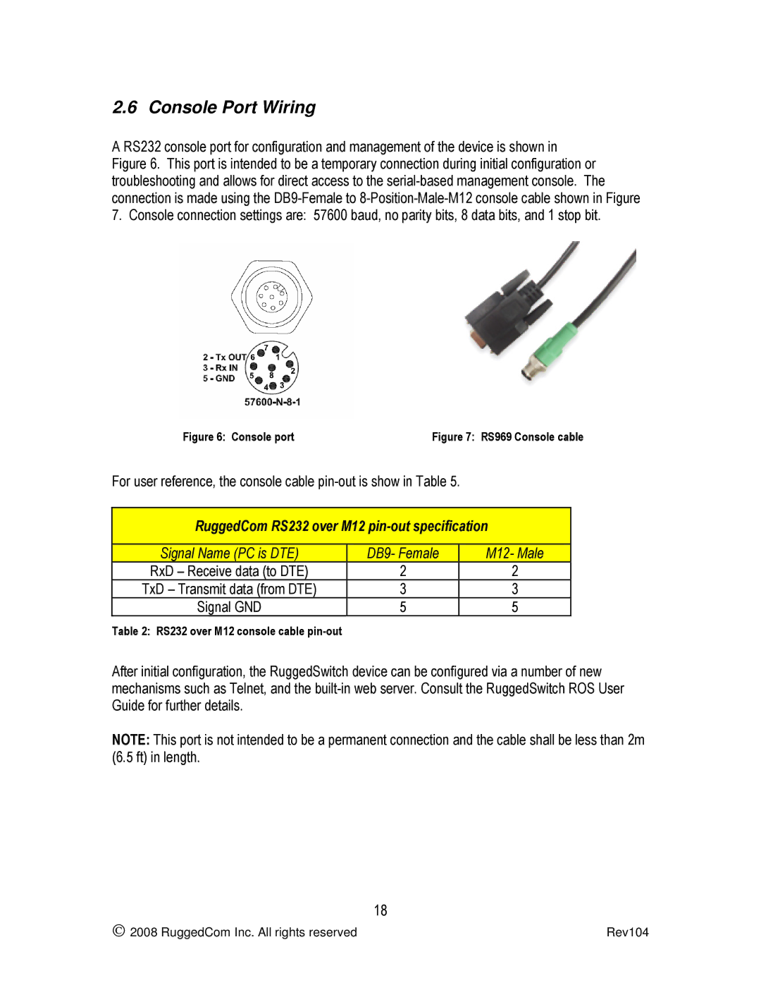
A RS232 console port for configuration and management of the device is shown in Figure 6. This port is intended to be a temporary connection during initial configuration or troubleshooting and allows for direct access to the
Figure 6: Console port | Figure 7: RS969 Console cable |
For user reference, the console cable
RuggedCom RS232 over M12
Signal Name (PC is DTE)
RxD – Receive data (to DTE) TxD – Transmit data (from DTE) Signal GND
Table 2: RS232 over M12 console cable pin-out
DB9- Female
2
3
5
M12- Male
2
3
5
After initial configuration, the RuggedSwitch device can be configured via a number of new mechanisms such as Telnet, and the
NOTE: This port is not intended to be a permanent connection and the cable shall be less than 2m (6.5 ft) in length.
18
2008 RuggedCom Inc. All rights reserved | Rev104 |