APPENDIX A
MODEL 3004-MTE SERIES
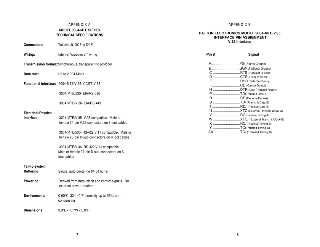
TECHNICAL SPECIFICATIONS
Connection: | Tail circuit, DCE to DCE |
Wiring:Internal
Transmission format::Synchronous, transparent to protocol
Data rate: | Up to 2.304 Mbps |
Functional interface:
Electrical/Physical
Interface:3004-MTE/V.35- V.35 compatible. Male or female
Tail-to-system
Buffering:Single,
Powering:Derived from data, clock and control signals. No
external power required.
Environment:
Dimensions: | 3.0"L x 1.7"W x 0.8"H |
APPENDIX B
PATTON ELECTRONICS MODEL
INTERFACE PIN ASSIGNMENT
V.35 Interface
Pin # | Signal |
A | FG (Frame Ground) |
B | SGND (Signal Ground) |
C | RTS (Request to Send) |
D | CTS (Clear to Send) |
E | DSR (Data Set Ready) |
F | CD (Carrier Detect) |
H | DTR (Data Terminal Ready) |
P | TD(Transmit |
R | RD (Receive |
S | TD/ (Transmit |
T | RD/ (Receive |
U | XTC (External Transmit |
V | RC(Receive |
W | XTC/ (External Transmit |
X | RC/ (Receive |
Y | TC(Transmit |
AA | TC/ (Transmit |
7 | 8 |