3.0 OPERATION
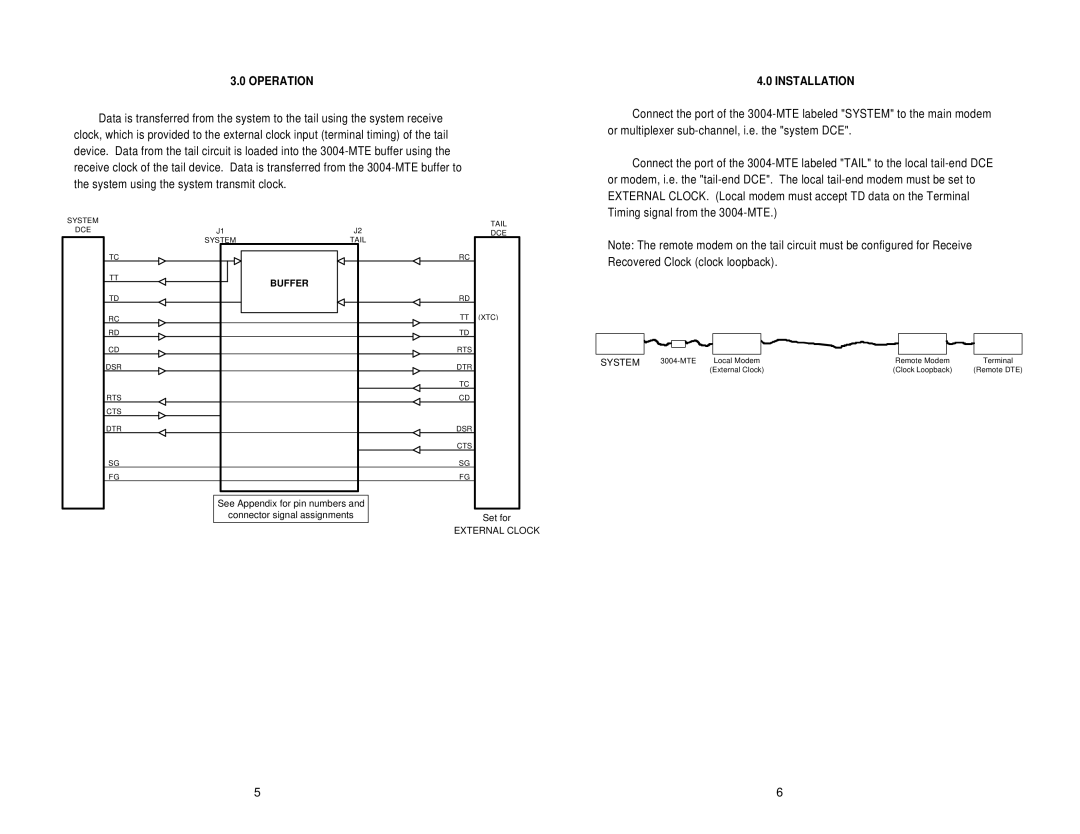
Data is transferred from the system to the tail using the system receive clock, which is provided to the external clock input (terminal timing) of the tail device. Data from the tail circuit is loaded into the
SYSTEM |
|
| TAIL | |
DCE | J1 | J2 | ||
DCE | ||||
| SYSTEM | TAIL |
| |
| TC |
| RC | |
| TT | BUFFER |
| |
|
|
| ||
| TD |
| RD | |
| RC |
| TT (XTC) | |
| RD |
| TD | |
| CD |
| RTS | |
| DSR |
| DTR | |
|
|
| TC | |
| RTS |
| CD | |
| CTS |
|
| |
| DTR |
| DSR | |
|
|
| CTS | |
| SG |
| SG | |
| FG |
| FG | |
| See Appendix for pin numbers and |
| ||
| connector signal assignments | Set for | ||
EXTERNAL CLOCK
EXTERNAL CLOCK
4.0 INSTALLATION
Connect the port of the
Connect the port of the
Note: The remote modem on the tail circuit must be configured for Receive Recovered Clock (clock loopback).
SYSTEM | Local Modem | Remote Modem | Terminal | |
|
| (External Clock) | (Clock Loopback) | (Remote DTE) |
5 | 6 |