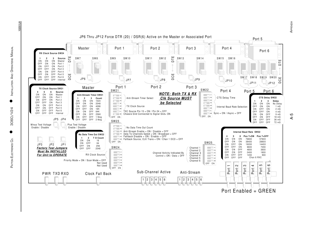
Patton electronic 3060/V24 manual Port Enabled = Green

Models: 3060/V24

1 22
Download 22 pages 8 Kb
Page 21
Image 21

102001UA

PATTON ELECTRONICS CO. 3060/V24 INSTALLATION AND OPERATIONS MANUAL


JP6 Thru JP12 Force DTR (20) / DSR(6) Active on the Master or Associated Port


Port 5


M a s t e r


Port 1

Port 2


Port 3


Port 4


Port 6


RX Clock Source SW24


1

2

3

Source

E

S W 7

S W 8

S W 9

S W 1 0

S W 1 1

S W 1 2

E

S W 1 3

S W 1 4

S W 1 5

S W 1 6


DT

DT


TE

O N

O N

O N

Master


O F F

O N

O N

Port 1


D

O N

O F F

O N

Port 2


O F F O F F

O N

Port 3


O N

O N

O F F

Port 4

E


E


O F F

O N

O F F

Port 5


O N

O F F

O F F

Port 6

D C


J P 7


J P 8

D C


J P 1 0

S W 1 7

S W 1 8

S W 1 9

S W 2 0

O F F

O F F

O F F

Internal


J P 6


J P 9


CE


J P 1 1


J P 1 2

D


Port 2


TX Clock Source SW21


M a s t e r


Port 1


Port 3

S W 2 2

Port 4


4

5

6

Source


S W 2 1


NOTE: Both TX & RX

Port 5

Port 6


O N

O N

O N

Master


Anti - Stream Timer SW21

1


1


O F F

O N

O N

Port 1


1

2

3

Count

2

Anti -Stream Timer Select

Clk Source MUST

2

CTS Delay Time


CTS Delay SW22

O N

O F F

O N

Port 2


3


O N

O N

O N

1 0 2 4

3


be Selected


1

2

3


Delay

O F F O F F

O N

Port 3


4


O F F

O N

O N

2 0 4 8

4


O N

O N

O N


No Delay

O N

O N

O F F

Port 4


O N

O F F

O N

4 0 9 6

5

TX Clock Source


5

Internal Baud Rate Selection

O F F

O N

O N


1 m S

O F F

O N

O F F

Port 5


6


O F F O F F O N

1 6 K

6


O N

O F F O N


2 m S

O N

O F F

O F F

Port 6


TXC Source Pin 15 = ON / Pin 24 = OFF


8 7


O N

O N

O F F

6 4 K

8 7


Sync = ON / Async = OFF

O F F

O F F

O N


4 m S

O F F

O F F

O F F

Internal


O F F

O N

O F F

2 5 6 K

Chassis Gnd Connected to Signal Gnd= ON


O N

O N

O F F


9 m S


O F F O N


J P 5 J P 4


O N O F F O F F

1 M e g

O F F O N


O F F O N O F F

1 8 m S


O F F O F F O F F

2 M e g

S W 2 3


O N O F F O F F

3 6 m S


O F F O F F O F F

7 2 m S


Minus Test Voltage

Plus Test Voltage

1


Enable / Disable

Enable / Disable

2

No Data Time Out Count


No Data Time Out SW23


1

2

T O Count


O N

O N

1 6

J P 3

J P 2

J P 1

O N

O F F

6 4

O F F

O N

2 5 6

Factory Test Jumpers

O F F

O F F

2 0 4 8

Must Be INSTALLED


For Unit to OPERATE


RX Clock Source

Priority Mode = ON / Scan Mode = OFF

Not Used

Not Used

6 5 4 3

O F F O N

S W 2 4

6 5 4 3 2 1

O F F O N

Anti - Stream Enable = ON / Disable = OFF

Data To Channels Gated = ON / Broadcast = OFF

Fallback Disable = ON / Enable = OFF

Fallback Source, CLK Trans = ON / Chan 1 DCD = OFF


Channel 1

Channel Activity Indicated By

Channel 2

Channel 3

Control = ON / Data = OFF

Channel 4


Channel 5


Channel 6

S W 2 5

6 5 4 3 2 1

O F F O N


Internal Baud Rate

SW22


4

5

6

Pos 7=ON

Pos 7=OFF

O N

O N

O N

7 6 8 0 0

5 7 6 0 0


O F F O N

O N

3 8 4 0 0

2 8 8 0 0


O N O F F O N

1 9 2 0 0

1 4 4 0 0


O F F O F F O N


9 6 0 0

7 2 0 0


O N

O N O F F


4 8 0 0

3 6 0 0


O F F O N O F F


2 4 0 0

1 8 0 0


O N O F F O F F


1 2 0 0

9 0 0


O F F O F F O F F


C h a n 6 R X C


1


2

3

4

5

6

APPENDIX

A-5

P W R T X D R X D

Clock Fall Back

Sub - Channel Active

Anti - Stream

1

2

3

4

5

6

1

2

3

4

5

6

Port


Port


Port


Port


Port


Port


Port Enabled = GREEN

Page 21
Image 21
Patton electronic 3060/V24 manual Port Enabled = Green

3060/V24 specifications

The Patton Electronic 3060/V24 is a cutting-edge digital communication solution that caters specifically to the need for versatile data transmission in various environments. This device is particularly well-suited for applications in enterprises, telecommunication networks, and industrial settings, delivering robust performance and reliability.

One of the standout features of the Patton Electronic 3060/V24 is its ability to support multiple protocols, making it highly adaptable to different communication standards. This flexibility ensures seamless integration into existing networks without the need for extensive changes or overhauls. Its support for synchronous and asynchronous data communication allows for efficient data transmission and enhances compatibility with legacy systems.

The device is equipped with advanced error correction technologies, ensuring the integrity and reliability of data during transmission over various mediums, including leased lines and IP networks. The use of sophisticated coding algorithms minimizes data loss and maximizes throughput, which is essential for businesses relying on critical communications.

In terms of characteristics, the Patton Electronic 3060/V24 boasts a user-friendly interface, simplifying configuration and management. With its intuitive web interface and SNMP support, network administrators can easily monitor performance metrics and troubleshoot issues in real-time. This ease of management helps reduce downtime and improves overall operational efficiency.

Moreover, the Patton Electronic 3060/V24 is designed with scalability in mind. It can easily expand to accommodate growing network demands, making it an ideal choice for organizations planning to future-proof their communication infrastructure. The device supports both copper and fiber connections, providing enhanced options for connectivity depending on the specific requirements of the deployment environment.

Power over Ethernet (PoE) capability further enhances its utility by allowing the device to receive power through the Ethernet cable, reducing the need for additional power outlets and simplifying installation in hard-to-reach areas.

In conclusion, the Patton Electronic 3060/V24 stands out as a versatile and reliable communication device that integrates advanced technologies to meet the demands of modern networks. Its flexibility, ease of management, and robust performance make it an ideal solution for businesses seeking to enhance their communication capabilities while ensuring reliability and efficiency.