2.0 GENERAL INFORMATION
Thank you for your purchase of this Patton Electronics product. This product has been thoroughly inspected and tested and is warranted for One Year parts and labor. If any questions or problems arise during installation or use of this product, please do not hesitate to contact Patton Electronics Technical Support at (301) 975-1007.
2.1FEATURES
•Provides "Star" distribution for seven AS/400 or 3X terminals
•Supports cost-effective unshielded twisted pair communication
•Active signal regeneration enables hub-to-terminal distances of 2250 ft and host-to-terminal distances of 4500 ft
•LED status indicators for each RJ-45 twisted pair port
•Transparent to data protocol—supports data rates to 1 Mbps
•100% compatible with Patton Model 410 Twinax baluns
•Separate signal-to-pin configuration for each port
•Transformer isolation at every port
2.2DESCRIPTION
The Patton Model 457B AllStarTM is an active seven port distribution hub for AS/400 and 3X systems. The Model 457B distributes one twisted pair 1Mbps host to seven twisted pair 1Mbps terminals. It is designed to be used in conjunction with Patton's Model 410 Series twinax baluns which adapt the host and terminal ports from twinax to twisted pair.
The Model 457B features modular RJ-45 ports on the seven terminal channels, and an RJ-45 port plus screw terminals on the host channel. The host and terminal can be at distances up to 2250 feet, and each terminal and its port can also be at distances up to 2250 feet. This yields a maximum host-to-terminal distance of 4500 ft, and a total aggregate cabling distance of 18,000 feet. The Model 457B has one LED per port to indicate data activity. For added convenience, each port has its own pair of internal straps that allow "tip" and "ring" to be assigned to any of the eight RJ-45 pins.
Optional 19" rack mount hardware allows two Model 457Bs to be installed side-by-side in a single 1U rack space. Additional space is conserved by operating the two rack mounted 457Bs from a single AC power supply harness. Power supplies of 120 or 240 volts are available for both stand alone and rack mount units.
3
3.0 CONFIGURATION
The Model 457B offers the option of configuring individual RJ-45 ports for specific twisted pair pin-outs. This section tells how to access and set the internally mounted jumpers for each port.
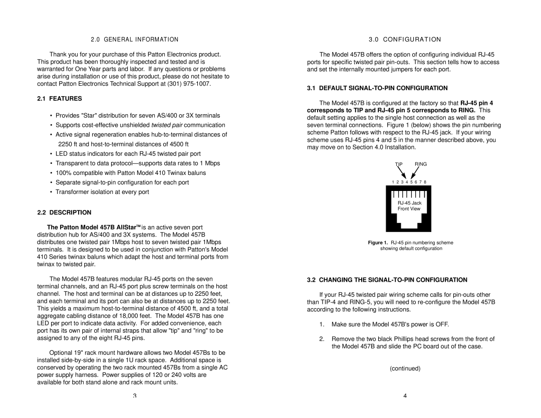
3.1 DEFAULT SIGNAL-TO-PIN CONFIGURATION
The Model 457B is configured at the factory so that RJ-45 pin 4 corresponds to TIP and RJ-45 pin 5 corresponds to RING. This default setting applies to the single host connection as well as the seven terminal connections. Figure 1 (below) shows the pin numbering scheme Patton follows with respect to the RJ-45 jack. If your wiring scheme uses RJ-45 pins 4 and 5 in the manner described above, you may move on to Section 4.0 Installation.
TIP RING
1 2 3 4 5 6 7 8
RJ-45 Jack
Front View
Figure 1. RJ-45 pin numbering scheme showing default configuration
3.2 CHANGING THE SIGNAL-TO-PIN CONFIGURATION
If your RJ-45 twisted pair wiring scheme calls for pin-outs other than TIP-4 and RING-5, you will need to re-configure the Model 457B according to the following instructions.
1.Make sure the Model 457B's power is OFF.
2.Remove the two black Phillips head screws from the front of the Model 457B and slide the PC board out of the case.
(continued)
4